Check patentability & draft patents in minutes with Patsnap Eureka AI!

Magnetic sensor with bridge circuit including magnetoresistance effect elements

A technology of magnetoresistance effect element and magnetic sensor, applied in the field of magnetic sensor, can solve the problems of electrical imbalance of bridge circuit, failure to consider shunt current, error of output voltage measurement value, etc., and achieve the effect of improving detection accuracy

Active Publication Date: 2011-03-23
TDK CORP
View PDF7 Cites 19 Cited by
  • Summary
  • Abstract
  • Description
  • Claims
  • Application Information

AI Technical Summary

Problems solved by technology

[0005] However, the above method fails to consider the shunt current flowing from the bridge circuit of the magnetic sensor to the external device (amplification circuit) during the measurement of the output voltage
The shunt current causes an electrical imbalance in the bridge circuit, resulting in an error in the measured value of the output voltage itself

Method used


Image

  • Magnetic sensor with bridge circuit including magnetoresistance effect elements
  • Magnetic sensor with bridge circuit including magnetoresistance effect elements
  • Magnetic sensor with bridge circuit including magnetoresistance effect elements

Examples


Embodiment Construction

[0013] Embodiments of the present invention will now be described with reference to the accompanying drawings.

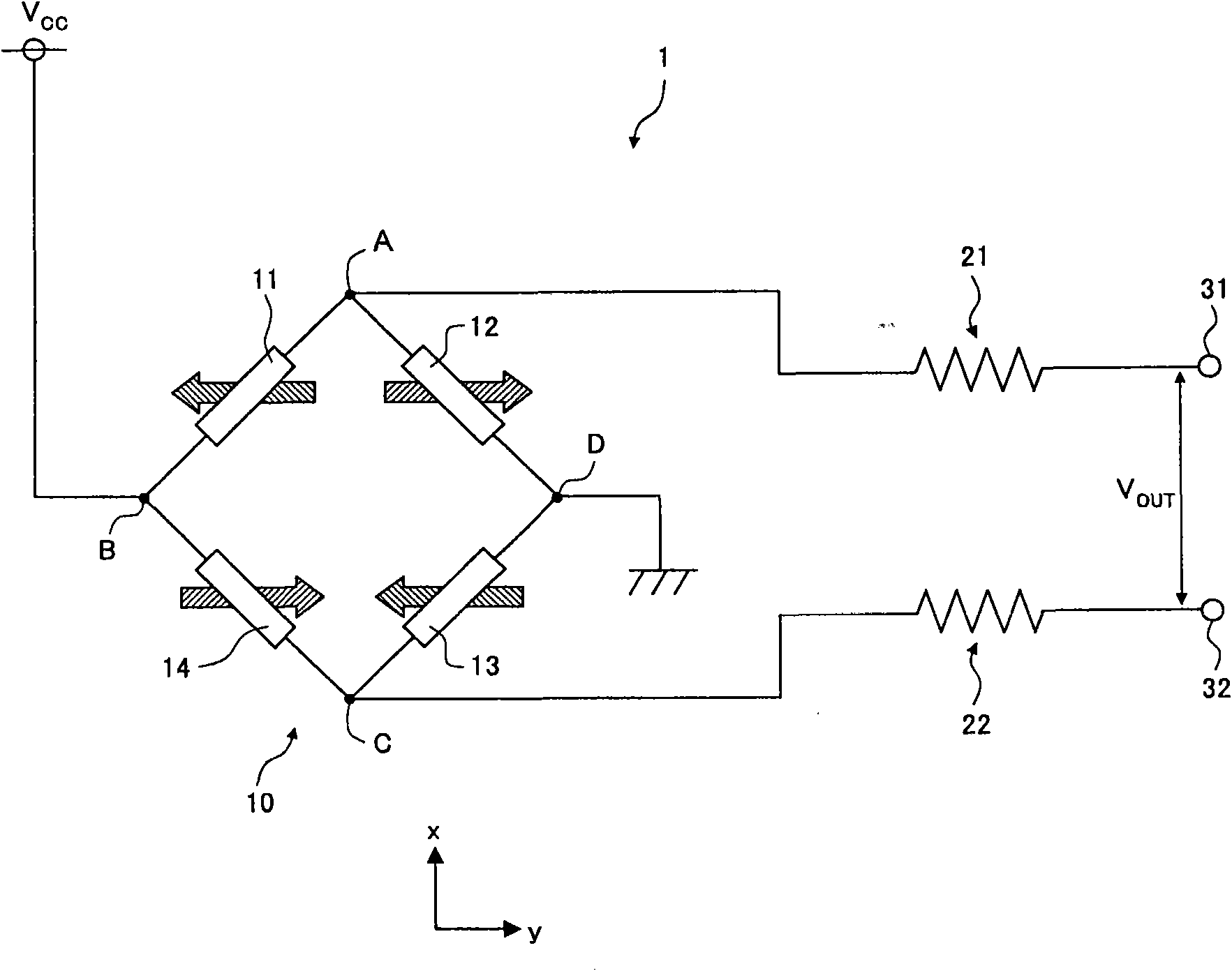
[0014] figure 1 is a circuit diagram showing the configuration of the magnetic sensor according to the present embodiment.

[0015] The magnetic sensor 1 of the present embodiment includes a bridge circuit 10 having four resistive element portions each including the same magnetoresistance effect elements (MR elements) 11-14. As described below, the bridge circuit 10 is configured to provide an output that varies according to the direction of the external magnetic field. An external device connected to the external connection terminals 31 , 32 reads an output through the external connection terminals 31 , 32 .

[0016] The bridge circuit 10 includes a parallel circuit in which a series circuit including the first and second MR elements 11 , 12 and a series circuit including the third and fourth MR elements 13 , 14 are connected in parallel to each other. Connectio...


PUM


Abstract

A magnetic sensor for detecting a direction of an external magnetic field comprises: a bridge circuit configured to provide an output that changes in accordance with the direction of the external magnetic field, the bridge circuit including four resistance element sections, each of which comprises at least one magnetoresistance effect element; and two resistors connected to respective output terminals of the bridge circuit. The ratio of the resistance of each of the resistors to that of the bridge circuit is at least 2 when the resistance of each of the resistance element sections is at a minimum corresponding to a change in magnetoresistance.

Description

technical field [0001] The present invention relates to a magnetic sensor, in particular to a magnetic sensor having a bridge circuit including a magnetoresistive effect element. Background technique [0002] In recent years, magnetic sensors have been used to detect the rotation angle of a rotator, such as a steering wheel in a vehicle. [0003] For example, JP 8-226960 discloses a magnetic sensor having a bridge circuit including a magnetoresistance effect element (MR element) configured to provide an output that changes according to the direction of an external magnetic field. In such a magnetic sensor, a magnet or the like is mounted on a rotator so that the direction of an external magnetic field changes according to the rotation of the rotator. The rotation angle of the spinner is detected by detecting the direction of the external magnetic field. Therefore, highly accurate detection of the direction of the external magnetic field is naturally required. For this rea...

Claims


Application Information

Patent Timeline
Patent Type & Authority Applications(China)
IPC IPC(8): G01R33/09
CPCG01R33/0029G01R33/0023G01R33/091
Inventor 猿木俊司平林启
Owner TDK CORP
Features
  • R&D
  • Intellectual Property
  • Life Sciences
  • Materials
  • Tech Scout
  • Unparalleled Data Quality
  • Higher Quality Content
  • 60% Fewer Hallucinations
Learn More