
Improved solar component frame structure

A solar module and frame technology, which is applied in the field of solar energy applications, can solve the problems of difficult to control the uniformity of sealing, difficult to guarantee sealing performance, and decreased electrical insulation, and achieves a simple structure, good sealing shock absorption, and improved sealing performance. Effect

Inactive Publication Date: 2011-03-23
TAITONG TAIZHOU IND
View PDF6 Cites 6 Cited by
  • Summary
  • Abstract
  • Description
  • Claims
  • Application Information

AI Technical Summary

Problems solved by technology

[0005] In the prior art, the solar module frame structure has the disadvantage of poor sealing performance
During the assembly process, especially when the module area is larger, due to the bow-shaped or wave-shaped characteristics of the tempered glass itself, and the center of gravity of the product itself is directed downward, the product will sag in the middle and the two ends will be upturned. Generally, when the frame is installed manually or pneumatically, a lot of sealant will be squeezed out from the grooves in the four corners. Although a large amount of silicone is injected at the beginning, the silicone on the upper and lower sides of the product is uneven, and some places even have no sealant. , the uniformity of sealing is difficult to control, the sealing performance is difficult to guarantee, the components are prone to delamination on the four sides of the product, and the electrical insulation is reduced.

Method used


Image

  • Improved solar component frame structure
  • Improved solar component frame structure
  • Improved solar component frame structure

Examples


Embodiment Construction

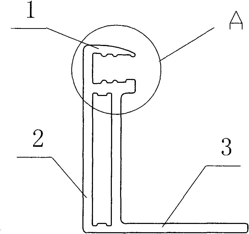
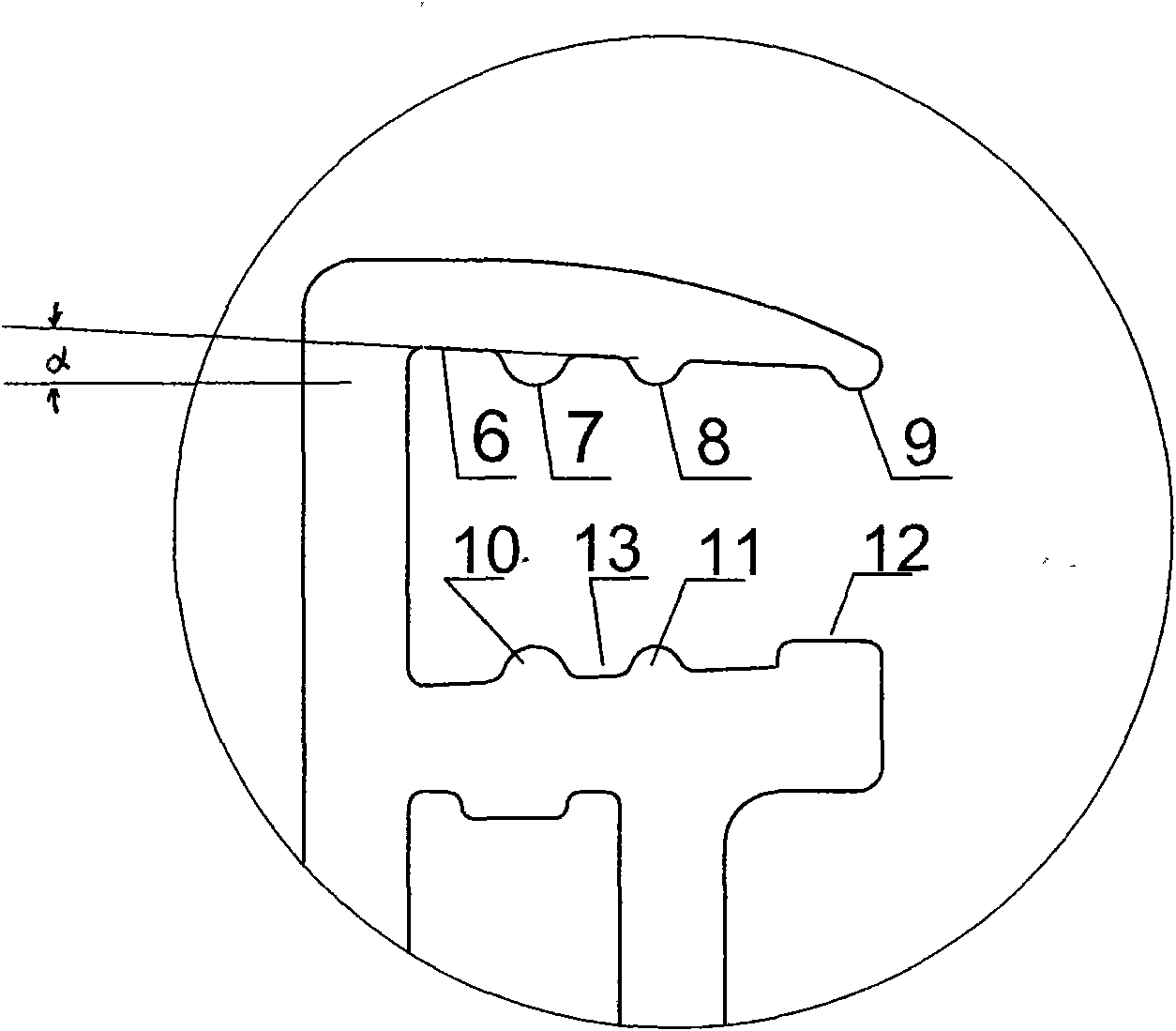
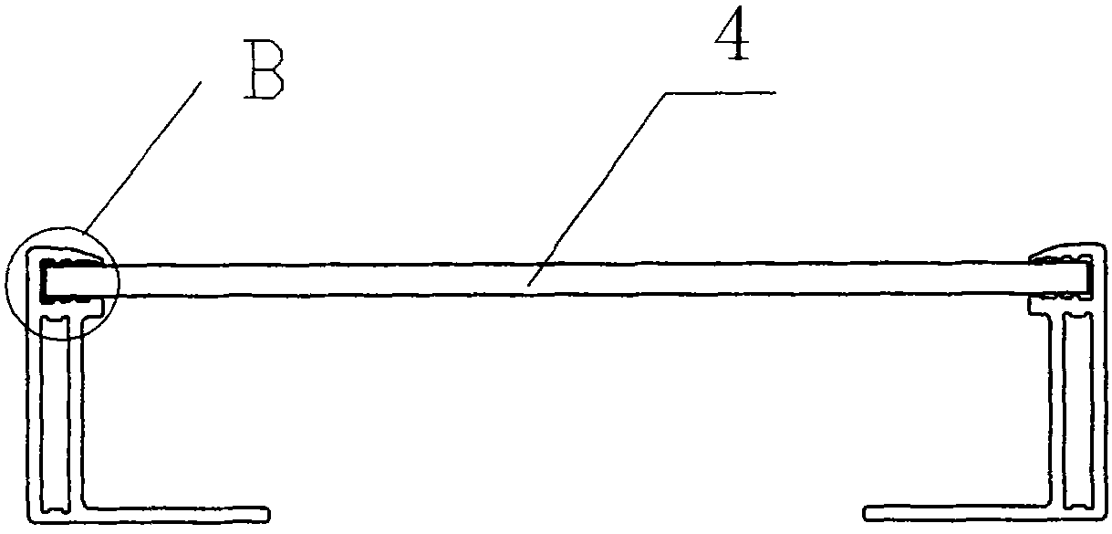
[0038] See attached Figure 1-4 , the improved solar module frame structure shown in Embodiment 1 of the present invention, the whole device is in the shape of an "L" as a whole, and it includes a frame body 1 that clamps a laminate 4, and is connected to the bottom of the frame body 1 The supporting edge 2 and the supporting foot 3, the longitudinal section of the frame frame body 1 is a frame shape with an opening towards the inside, and ribs 7, 8, 9 are distributed on the inner upper surface of the frame frame body, and the inside of the frame frame body Ribs 10, 11, 12 are distributed on the lower surface, and each rib is parallel to the inner side of the frame body. The upper and lower surfaces of the frame body inside the above-mentioned frame body each have an inclination angle of 3°, and the height of ribs 7, 8, 10, 11 Both are 0.85mm, the height of rib 9 is 1.00mm, and the longitudinal section of rib 12 closest to the frame-shaped opening on the inner lower surface of...


PUM

PropertyMeasurementUnit
Bottom lengthaaaaaaaaaa

Abstract

The invention relates to an improved solar component frame structure with good sealing property. The whole device is in an L shape as a whole, and comprises a frame body, a supporting foot and a supporting edge, wherein the frame body clamps a laminated part; the supporting foot and the supporting edge are connected with the lower part of the frame body; the longitudinal section of the frame body is in a frame shape open toward the inside direction; adhesive for bonding is arranged on the upper surface and the lower surface in the frame body; the invention is characterized in that a plurality of ribs are distributed on both the upper surface and the lower surface in the frame body; each rib is parallel to the inner side edge of the frame body; each of the upper surface and the lower surface in the frame body incline for respectively a certain inclination angle; and the longitudinal section of the rib, which is the nearest to a frame-shaped opening, on the lower surface in the frame body, is in a trapezoid shape. The invention has the advantages of even and full distribution of the adhesive for bonding, good sealing property, simple structure and stable and reliable mechanical strength, is convenient in installation, effectively prevents rainwater corrosion, resists wind and snow load, and ensures long-term stable outdoor working of the solar component.

Description

(1) Technical field: [0001] The invention relates to an improved solar component frame structure, which belongs to the technical field of solar energy applications. (two) background technology: [0002] Solar energy is a kind of green and clean energy, and the governments of various countries are vigorously supporting the solar energy industry. Solar module is the basic device of photovoltaic solar energy industry, which generates photoelectric current after being irradiated by sunlight. It is composed of battery cells connected by wires, then packaged, and finally installed with the upper frame. Specifically, it is composed of tempered glass, EVA, cells, EVA, and backplane TPT in sequence and laminated into a whole by a laminator. , and then install the upper frame to form a component, and finally install the aluminum frame. The longitudinal section of the frame body is in the shape of a frame with openings towards the inside. During assembly, silicone is injected into th...

Claims


Application Information

Patent Timeline
IPC IPC(8): H01L31/02H01L31/0203H02S30/10
CPCY02E10/50
Inventor 王兴华
Owner TAITONG TAIZHOU IND
Learn More