Blade pitch lock device

A locking device and blade technology, applied in wind power generation, engine components, wind turbines, etc., can solve the problems of dependence, increase the risk of failure, expensive, etc., and achieve the effect of high safety

Inactive Publication Date: 2011-03-30
GE WIND ENERGY NORWAY
View PDF5 Cites 11 Cited by
  • Summary
  • Abstract
  • Description
  • Claims
  • Application Information

AI Technical Summary

Problems solved by technology

A disadvantage associated with many similar conventional systems is that they rely on external forces in order to function properly, which increases the risk of some kind of failure (eg in the event of a power outage)
Also, many of the adjustment mechanisms and locks rely on electrical control systems, which are complex and expensive to install and maintain (both)

Method used


Image

  • Blade pitch lock device
  • Blade pitch lock device
  • Blade pitch lock device

Examples


Embodiment Construction

[0023] The following detailed description and the examples contained therein are provided merely for the purpose of describing and illustrating certain embodiments of the invention, and they are not intended in any way to limit the scope of the invention.

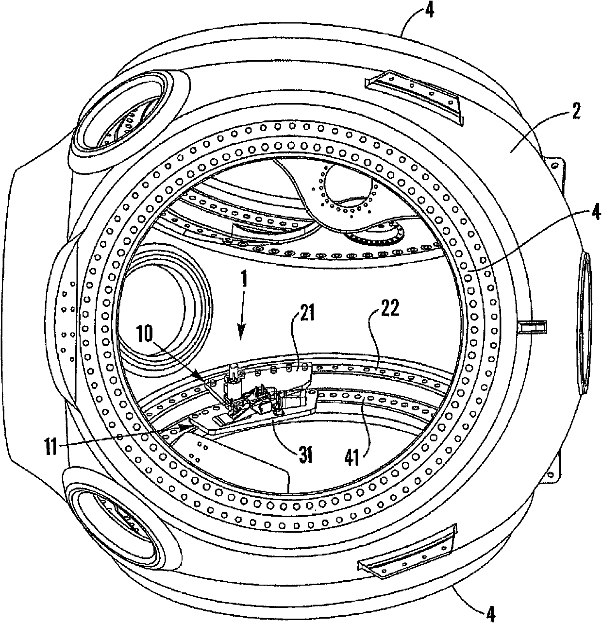
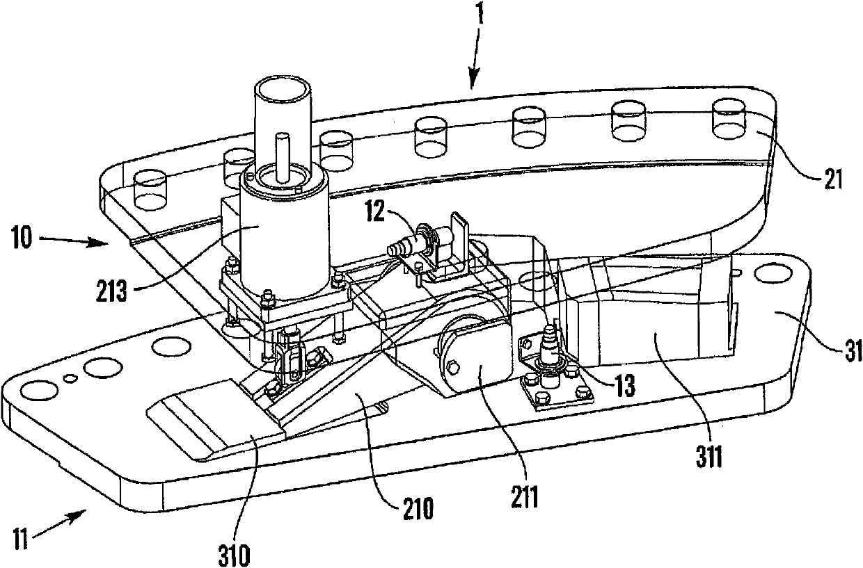
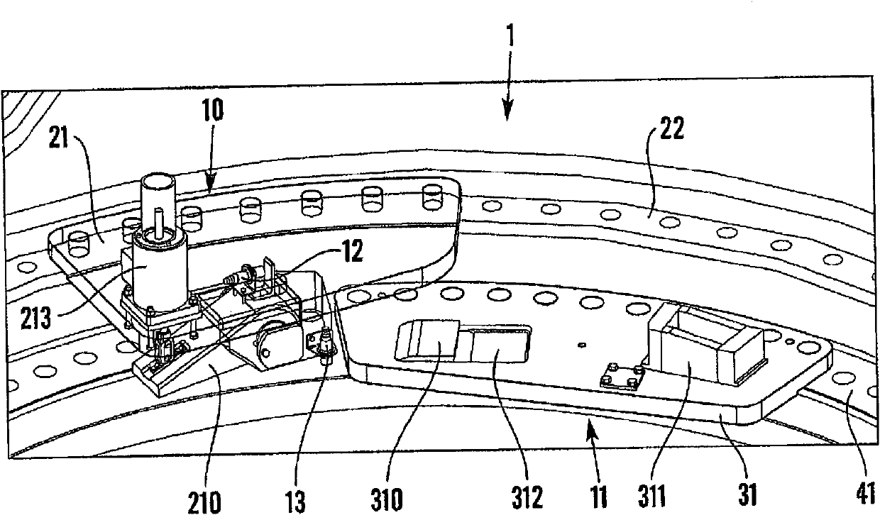
[0024] figure 1 A rotor hub 2 of a wind energy plant is shown with three pitch bearings 4 each intended to receive a turbine blade (not shown). Each pitch bearing 4 comprises an annular flange 22 connected to the hub 2, and an annular bearing ring 41 configured for operative connection with a rotor blade. A pitch bearing 4 is seen comprising a locking device 1 according to the invention. figure 1 The locking device 1 in is shown in a locking mode, thereby preventing a blade (not shown) from rotating about its longitudinal axis relative to the rotor hub 2 . as by figure 1 As shown, the locking device 1 comprises a hub part 10 connected to the flange 22, and a blade part 11 connected to the bearing ring 41 of the rotor bla...


PUM


Abstract

The invention relates to a blade pitch lock device. A locking device for locking a turbine blade of a wind power plant at a predetermined pitch angle, which wind power plant includes a rotor hub and at least one turbine blade where the blade root of the at least one turbine blade is connected to the rotor hub through a pitch bearing so that the pitch angle of the at least one turbine blade is adjustable by turning of the at least one turbine blade about its longitudinal axis relative to the rotor hub and wherein the device for locking the turbine blade includes a mechanical snap-in mechanism which in a locked position prevents the at least one turbine blade from turning about its longitudinal axis thus fixating the at least one turbine blade in the predetermined pitch angle.

Description

technical field [0001] The invention relates to a device for locking a turbine blade of a wind energy installation at a predetermined pitch angle, the wind energy installation comprising a rotor hub and at least one turbine blade, wherein the blade root of the at least one blade is connected to the on the rotor hub so that the pitch angle of the at least one blade can be adjusted by rotating the at least one blade about its longitudinal axis relative to the rotor hub. Background technique [0002] Adjusting the pitch angle of the turbine blades is one way of controlling the rotational speed (rpm) of the wind turbine. To reduce load or stop rotation altogether, the blades are directed to a feathered position where the wind will not engage the blades and the blades are forced to stall and the rotation of the turbine will slow and / or stop. Once the turbine is stopped and the blades have been placed in the parked position, it is important that the pitch angle of the blades is n...

Claims


Application Information

Patent Timeline
Patent Type & Authority Applications(China)
IPC IPC(8): F03D7/00
CPCY02E10/723F03D7/0224F05B2260/79Y02E10/72F03D7/022F03D1/0664
Inventor M·林德贝里J·赫德贝里
Owner GE WIND ENERGY NORWAY
Why Eureka
Try Eureka