
LED lamp structure and heat dissipation method thereof

A technology of LED lamps and heat dissipation methods, which is applied in the direction of lighting and heating equipment, cooling/heating devices of lighting devices, and damage prevention measures of lighting devices. The heat dissipation conditions are consistent and the effect of increasing the heat dissipation effect

Inactive Publication Date: 2011-03-30
LEOTEK ELECTRONICS
View PDF0 Cites 2 Cited by
  • Summary
  • Abstract
  • Description
  • Claims
  • Application Information

AI Technical Summary

Problems solved by technology

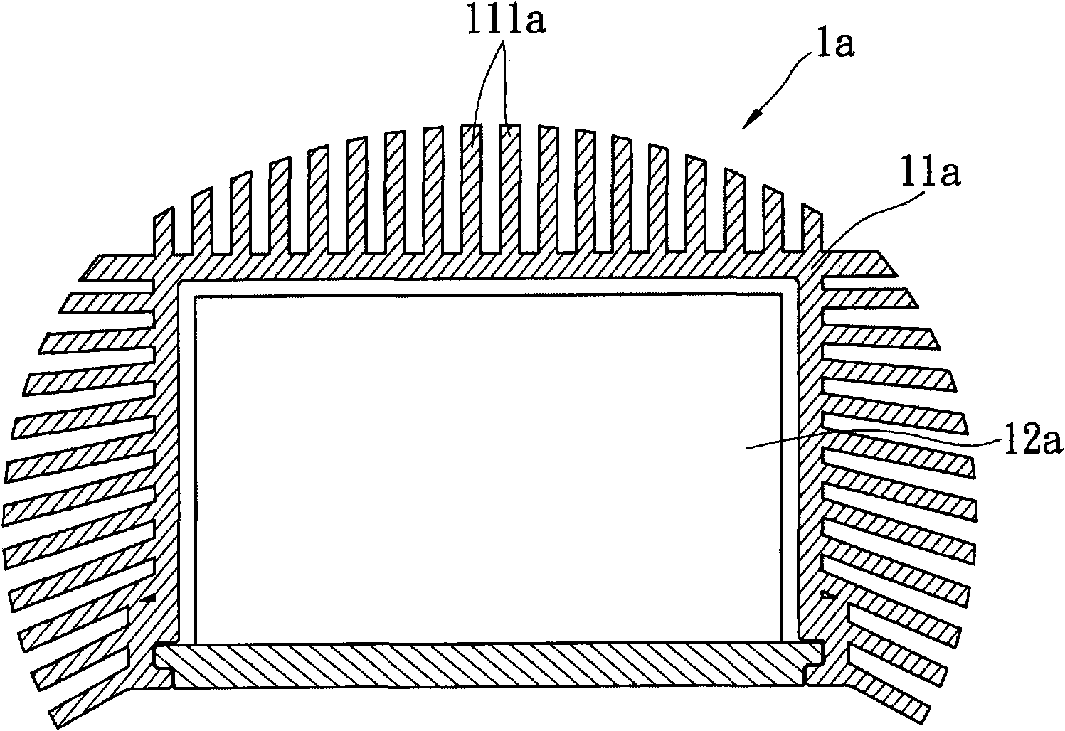
However, the casing 11a often accumulates dust and affects heat dissipation, and the casing 11a needs to increase its thickness to spread the heat evenly, and it must be made of metal die-casting with good thermal conductivity, resulting in increased system cost and weight
[0005] 2. There is another LED lamp that uses heat pipes (not shown in the figure) to export the heat generated by light-emitting diodes. However, adding heat pipes will increase the system cost and make maintenance difficult. At the same time, the system volume and complexity will increase, making it difficult to assemble
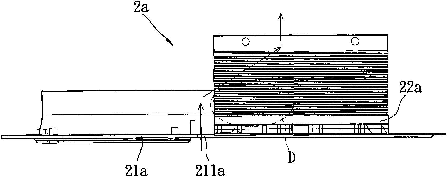
When the wind blows into the lamp through the air inlet 211a (the air flow path is shown in the figure), some parts of the LED light source device 22a cannot be blown by the wind, forming a dead zone D in the flow field, which affects the heat dissipation effect

Method used


Image

  • LED lamp structure and heat dissipation method thereof
  • LED lamp structure and heat dissipation method thereof
  • LED lamp structure and heat dissipation method thereof

Examples


Embodiment Construction

[0065] see Figure 4 to Figure 8 , The present invention provides an LED lamp structure, including: a casing 1 , at least one LED light source module 2 and a power supply 3 .

[0066] The housing 1 is a hollow box, which can be made of sheet metal or plastic. The casing 1 includes a cover 11 and a base 12 . In the present embodiment, the cover 11 is pivotally mounted on the base 12 , but not limited thereto. The cover 11 and the base 12 form a cooling space 13 .

[0067] The cover body 11 is provided with a plurality of air outlets 111 , a plurality of depressions 112 and a groove 113 . The air outlets 111 of the cover 11 are elongated, spaced apart from each other on the top of the cover 11 , and located on two sides of the groove 113 . These recesses 112 are respectively located at the air outlet 111 and are vertically lower than the cover 11 . Two ends of the recesses 112 are respectively connected to the cover 11 to prevent dust or rainwater from directly entering the ho...


PUM


Abstract

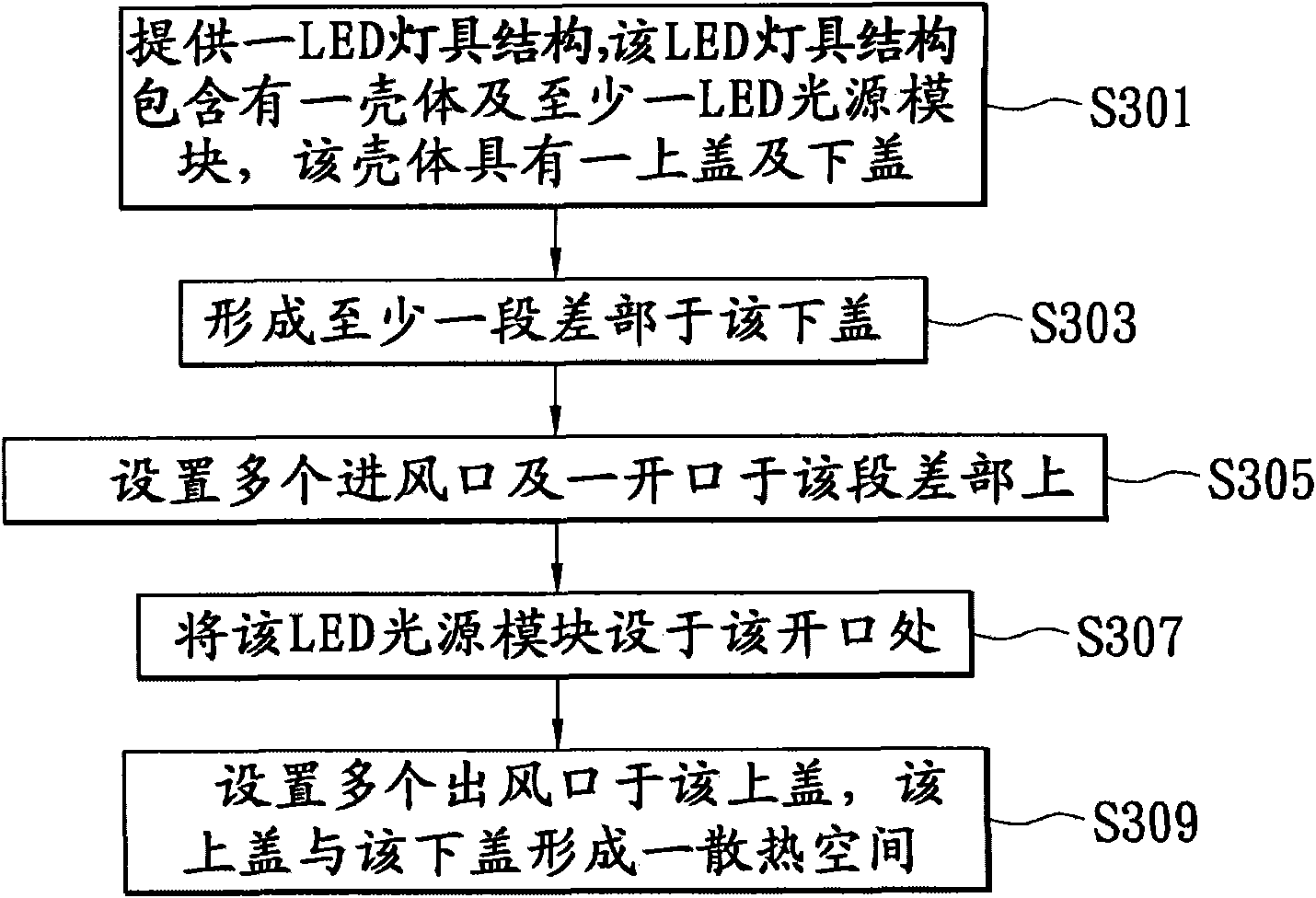
The invention provides a heat dissipation method for an LED lamp structure. The method comprises the following steps of: providing an LED lamp, wherein the LED lamp comprises a shell and at least one LED light source module, the shell is provided with a cover body, a base and a plurality of air outlets, at least one section difference part is formed in the base, the inclined plane of the section difference part is provided with a plurality of air inlets, the LED light source module is close to the air inlets, the LED light source module is provided with a heat dissipation device and the shell is provided with a plurality of air outlets; guiding atmospheric flow to a heat dissipation space formed by the cover body and the base from the air inlets along the inclined plane of the section difference part; when an LED generates heat energy, blowing the atmospheric flow entering the heat dissipation space to the heat dissipation device along the flow field direction to take away the heat energy; and discharging the atmospheric flow with the heat energy from the air outlets to dissipate the heat energy to the atmosphere. Therefore, the method has the advantages of smooth heat dissipation, uniform flow field distribution and extensibility, is easy in production, effectively reduces the manufacturing cost and relieves the weight. The invention also provides the LED lamp structure.

Description

technical field [0001] The invention relates to an LED lamp structure and a heat dissipation method thereof, in particular to an LED lamp structure and a heat dissipation method with smooth heat dissipation, uniform flow field distribution, effective cost reduction and weight reduction. Background technique [0002] Due to the advantages of high brightness, power saving and long life, light emitting diodes (LEDs) are widely used in lighting of various lamps, for example, LED lamps for road lighting are one example. However, light-emitting diodes generate a lot of heat when they emit light, and have poor heat resistance. Usually, heat dissipation devices must be used to remove the generated heat, so that the light-emitting diodes can emit light at an appropriate temperature without being burned. Therefore, if the heat dissipation design is not good, the high temperature will cause the brightness of the light-emitting diode itself to decrease, the lifespan will be shortened, a...

Claims


Application Information

Patent Timeline
Patent Type & Authority Applications(China)
IPC IPC(8): F21V29/00F21V15/02F21V11/18F21Y101/02F21V29/503F21V29/74F21V29/83
Inventor 胡胜雄
Owner LEOTEK ELECTRONICS
Learn More