Method and device for monitoring status of rotating diode of magnetizing exciter

A technology of rotating diodes and exciters, applied in the direction of measuring devices, measuring electricity, and measuring electrical variables, etc., can solve the problems of increased diode branch current, affecting the normal operation of the exciter, and equipment damage, etc., to improve reliability and stability Sexuality, the effect that is conducive to normal operation

Active Publication Date: 2011-03-30
CHINA NUCLEAR POWER TECH RES INST CO LTD +2
View PDF4 Cites 9 Cited by
  • Summary
  • Abstract
  • Description
  • Claims
  • Application Information

AI Technical Summary

Problems solved by technology

When the rated power of the exciter is running, the DC current provided by the rotating rectifier must meet a certain value. Once there is a short circuit or breakdown of the diode on the rectifier, the fuse is blown or the diode itself is disconnected. The rectifier branch is disconnected phenomenon, it will inevitably lead to an increase in the current of other branches or diode branches connected in parallel with it. If the increase in current exceeds the fuse capacity of the insurance, it will cause other branches to withdraw from operation, thereby affecting the normal operation of the exciter, or even Cause damage to the equipment connected to the exciter

Method used


Image

  • Method and device for monitoring status of rotating diode of magnetizing exciter
  • Method and device for monitoring status of rotating diode of magnetizing exciter
  • Method and device for monitoring status of rotating diode of magnetizing exciter

Examples


Embodiment Construction

[0057]The following will clearly and completely describe the technical solutions in the embodiments of the present invention with reference to the accompanying drawings in the embodiments of the present invention. Obviously, the described embodiments are only some, not all, embodiments of the present invention. Based on the embodiments of the present invention, all other embodiments obtained by persons of ordinary skill in the art without creative efforts fall within the protection scope of the present invention.

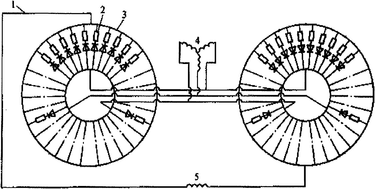
[0058] It should be noted that the state monitoring device for the rotating diode of the exciter according to the embodiment of the present invention is suitable for the state monitoring of the rotating diode of the exciter of the rectifier including positive and negative pole rings.

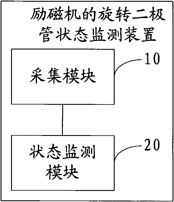
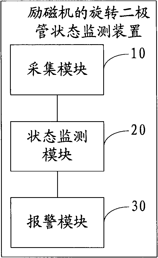
[0059] See figure 2 , is a structural schematic diagram of the first embodiment of the rotating diode state monitoring device of the exciter of the present invention; the device incl...


PUM


Abstract

The embodiment of the invention discloses a method for monitoring the status of a rotating diode of a magnetizing exciter, which comprises the following steps of: collecting a rotating diode signal and a phase discrimination pulse signal of the magnetizing exciter; and analyzing the collected rotating diode signal and the collected phase discrimination pulse signal to determine the status of the rotating diode. The embodiment of the invention also discloses a device for monitoring the status of the rotating diode of the magnetizing exciter. The method and the device are used for monitoring the status of the rotating diode in a rotating rectifier, so that the failed rotating diode can be treated in time, and the normal operation of the magnetizing exciter is ensured.

Description

technical field [0001] The invention relates to the technical field of generators, in particular to a method and device for monitoring the state of a rotating diode of an exciter. Background technique [0002] The exciter, that is, the excitation generator, generally adopts three-phase alternating current, and uses a rotating rectifier with a three-phase bridge rectification structure for current rectification to provide the DC current required for power generation. A rotary rectifier with a three-phase bridge rectification structure applied to an exciter, which includes rectifiers with positive and negative pole rings, and each phase of each pole ring of the rectifier is equipped with multiple diodes, and each phase Multiple diodes are connected in parallel and evenly distributed on the rectification ring. [0003] See figure 1 , is the structural schematic diagram of the existing exciter; wherein, 1 is the connection line, 2 is the diode assembly in the rotating rectifie...

Claims


Application Information

Patent Timeline
IPC IPC(8): G01R31/27
Inventor 刘业胜李建华夏敬明黄超杨勇钟质飞陆秀生李利徐小明尹亮许航源刘斌郭振武
Owner CHINA NUCLEAR POWER TECH RES INST CO LTD
Why Eureka
Try Eureka