Branch state monitoring method and device of rotary rectifier

A technology of rotating rectifiers and rectifiers, which is applied in the direction of emergency protection circuit devices, electromechanical devices, electrical components, etc., can solve the problems of affecting the normal operation of generators, increasing the current of other branches, and damaging equipment, so as to facilitate normal operation and improve Effects on Reliability and Stability

Inactive Publication Date: 2011-04-06
CHINA NUCLEAR POWER TECH RES INST CO LTD +1
View PDF4 Cites 9 Cited by
  • Summary
  • Abstract
  • Description
  • Claims
  • Application Information

AI Technical Summary

Problems solved by technology

When the generator is running at rated power, the DC current provided by the rotating rectifier must meet a certain value. Once there is a short circuit or breakdown of the diode on the branch on the rectifier, the fuse is blown or the diode itself is disconnected. The disconnection of the branch circuit will inevita

Method used


Image

  • Branch state monitoring method and device of rotary rectifier
  • Branch state monitoring method and device of rotary rectifier
  • Branch state monitoring method and device of rotary rectifier

Examples


Embodiment Construction

[0064] The following will clearly and completely describe the technical solutions in the embodiments of the present invention with reference to the accompanying drawings in the embodiments of the present invention. Obviously, the described embodiments are only some, not all, embodiments of the present invention. Based on the embodiments of the present invention, all other embodiments obtained by persons of ordinary skill in the art without creative efforts fall within the protection scope of the present invention.

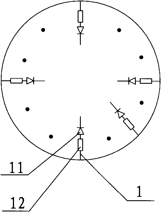
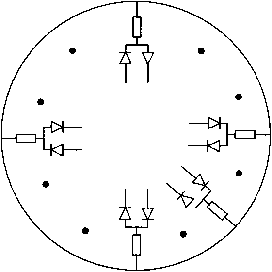
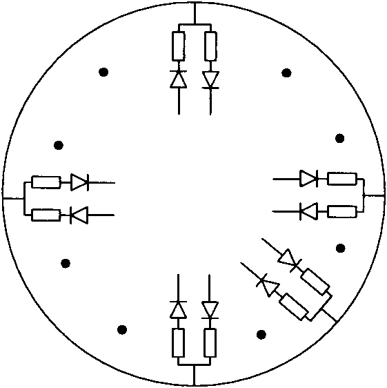
[0065] It should be noted that the embodiment of the present invention is applicable to a rotary rectifier in which the positive and negative diodes consist of a rectifying ring, that is, it is suitable for Figure 1-Figure 3 The rotary rectifier shown.

[0066] See Figure 4 It is a schematic structural diagram of the first embodiment of the branch state monitoring device of the rotary rectifier of the present invention; the device includes:

[0067] An acquisiti...


PUM


Abstract

The embodiment of the invention discloses a branch state monitoring method of a rotary rectifier, which comprises the following steps of: obtaining the rotating period of the rotary rectifier; sequentially obtaining conducting branch signals of the rotary rectifier in the period; carrying out analysis processing on the conducting branch signals in the period; and determining the branch state of the rotary rectifier. The embodiment of the invention also discloses a branch state monitoring device of the rotary rectifier. When the branch state monitoring method and the branch state monitoring device are adopted, the branch state of the rotary rectifier can be monitored so that faults generated in branches can be processed in time to ensure the normal operation of a generator.

Description

technical field [0001] The invention relates to the technical field of generators, in particular to a method and device for monitoring the state of a rotating diode of an exciter. Background technique [0002] In order for the generator to generate electricity, a space magnetic field needs to be established between the generator rotor and the stator, so that the stator winding of the generator cuts the alternating space magnetic field during the relative movement between the stator and the rotor, thereby generating electric energy. Generally, the above-mentioned spatial magnetic field necessary for generating electric energy is formed by adding direct current to the rotor winding. Since the current generated by the excitation system of the generator is alternating current, it is necessary to convert the alternating current into direct current through a device, which is the rotating rectifier of the generator. [0003] The rotary rectifier of the generator is generally a bra...

Claims


Application Information

Patent Timeline
IPC IPC(8): H02K29/06H02K11/00H02H7/06H02K11/20
Inventor 刘业胜李建华杨勇钟质飞陆秀生
Owner CHINA NUCLEAR POWER TECH RES INST CO LTD
Why Eureka
Try Eureka