Band-gap reference voltage detection circuit
A technology of reference voltage and detection circuit, applied in the direction of measuring current/voltage, measuring device, adjusting electrical variables, etc., can solve the problems of false alarm, inability to guarantee VREF2, and inability to correctly provide the ready signal of the bandgap reference voltage.
- Summary
- Abstract
- Description
- Claims
- Application Information
AI Technical Summary
Problems solved by technology
Method used
Image


Examples
Embodiment Construction
[0011] The technical solution of the present invention will be described in detail below in conjunction with the accompanying drawings and specific embodiments.
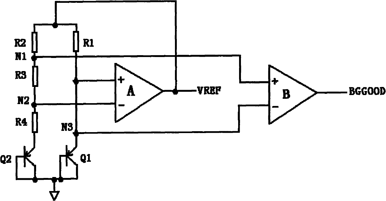
[0012] like figure 1 Shown is a preferred embodiment of the present invention, the bandgap reference voltage detection circuit includes a PN junction diode mainly composed of transistor Q1 and transistor Q2, comparator A, comparator B, resistor R1, resistor R2, resistor R3 and resistor R4;
[0013] Wherein, the collector of the transistor Q1 is respectively connected to the anode of the comparator A, the cathode of the comparator B and one end of the resistor R1 through the third node N3, and the other end of the resistor R1 is respectively connected to one end of the resistor R2 and the VREF output of the comparator A The other end of the resistor R2 is respectively connected to the positive pole of the comparator B and one end of the resistor R3 via the first node N1, and the other end of the resistor R3 is connec...
PUM
 Abstract
Description
Claims
Application Information
 - R&D
- Intellectual Property
- Life Sciences
- Materials
- Tech Scout
- Unparalleled Data Quality
- Higher Quality Content
- 60% Fewer Hallucinations
Browse by: Latest US Patents, China's latest patents, Technical Efficacy Thesaurus, Application Domain, Technology Topic, Popular Technical Reports.
© 2025 PatSnap. All rights reserved.Legal|Privacy policy|Modern Slavery Act Transparency Statement|Sitemap|About US| Contact US: help@patsnap.com