
Control circuit and control method of capacitive touch pad as well as application thereof

A technology of capacitive touch control and control circuit, which is applied in the direction of electrical pulse generator circuit, electrical components, electrical digital data processing, etc., can solve the problem of increasing parasitic capacitance, limited improvement of performance, and increase of basic capacitance of capacitive touch panel. Large and other problems, to achieve the effect of increasing the amount of induction, improving performance, and providing shielding effect

Inactive Publication Date: 2014-12-03
ELAN MICROELECTRONICS CORPORATION
View PDF4 Cites 0 Cited by
  • Summary
  • Abstract
  • Description
  • Claims
  • Application Information

AI Technical Summary

Problems solved by technology

Although the known differential detection method increases the amount of capacitance change, it also increases the parasitic capacitance between adjacent sensors, resulting in an increase in the basic capacitance of the capacitive touch panel, so the degree of performance improvement is limited

Method used


Image

  • Control circuit and control method of capacitive touch pad as well as application thereof
  • Control circuit and control method of capacitive touch pad as well as application thereof
  • Control circuit and control method of capacitive touch pad as well as application thereof

Examples


Embodiment Construction

[0074] The present invention will be further described below in conjunction with embodiment and accompanying drawing.

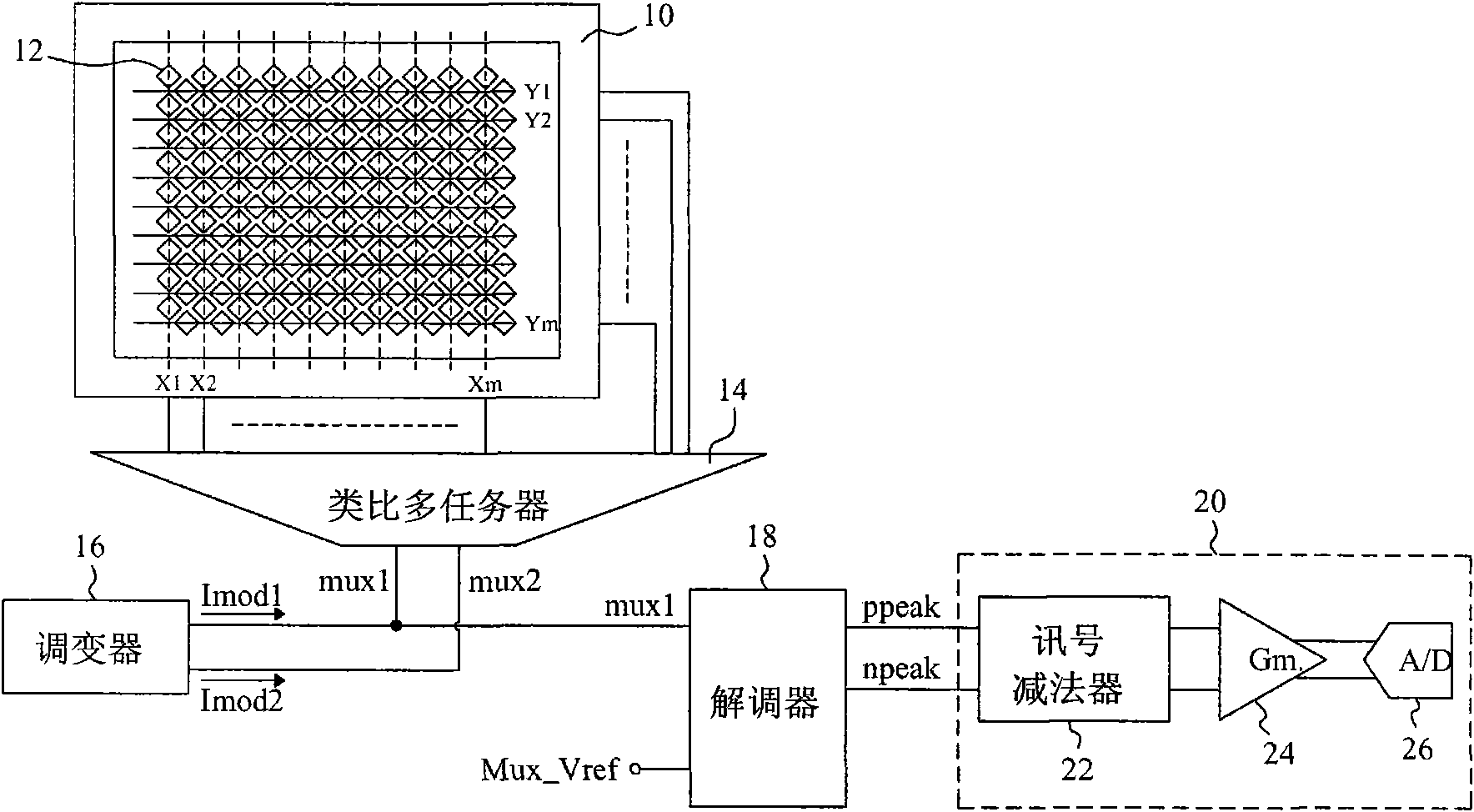
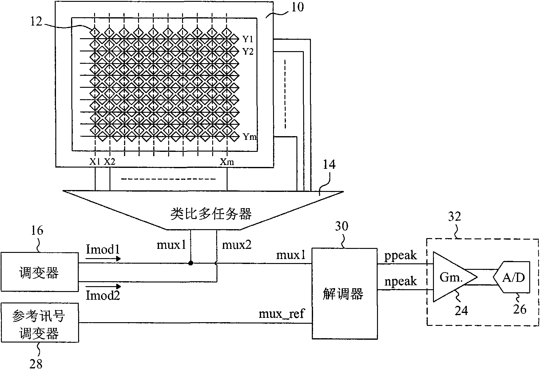
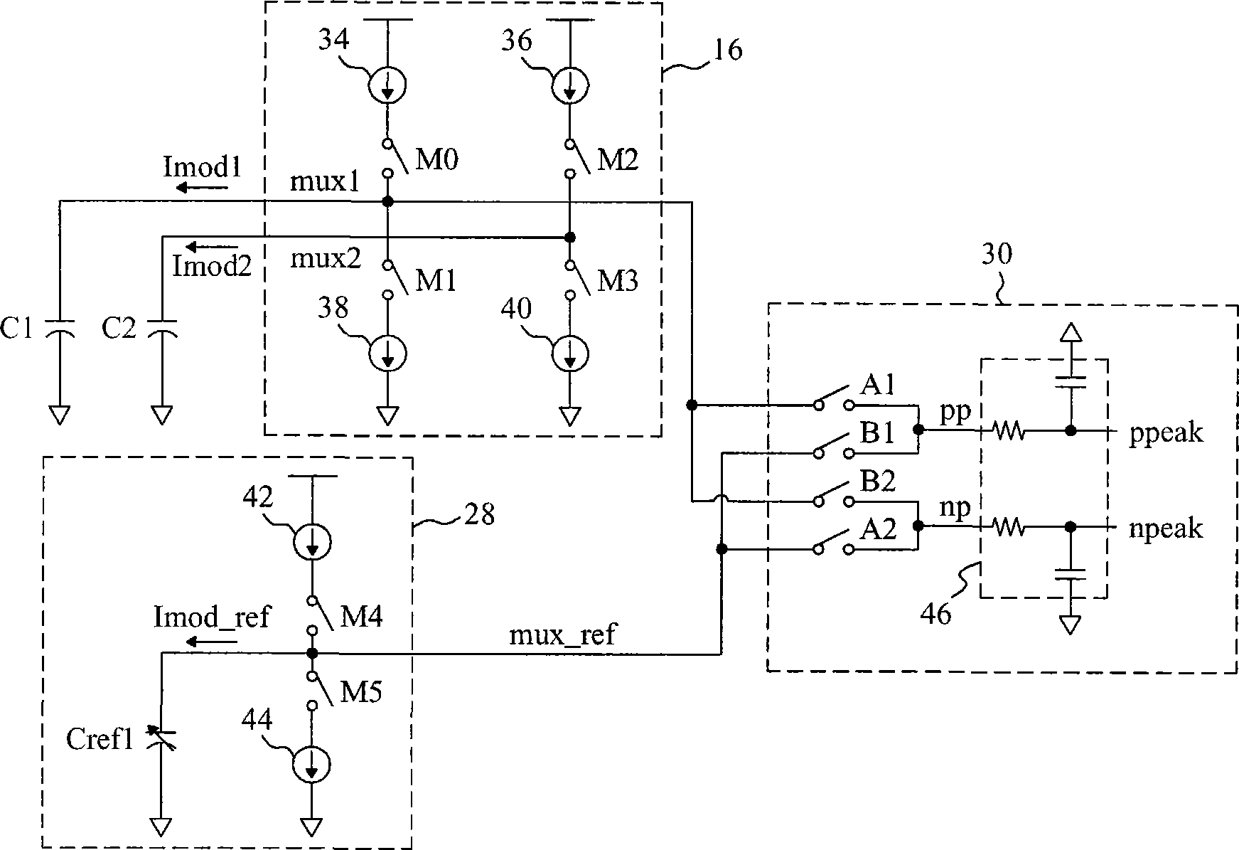
[0075] see now figure 2 , figure 2 is a schematic diagram according to an embodiment of the present invention. As shown in the figure, the capacitive touch panel 10 is generally made of glass material, plastic film or printed circuit board, and a plurality of sensors 12 arranged in patterns of metal, indium tin oxide conductive film or other materials are distributed on it. The sensor 12 forms X-direction traces X1-Xm and Y-direction traces Y1-Ym. The current signals Imod1 and Imod2 provided by the modulator 16 are applied to the selected traces through the analog multiplexer 14, and are modulated to generate modulation signals mux1 and mux2, and the reference signal modulator 28 is modulated to generate a reference signal mux_ref for demodulation The converter 30 demodulates the signal mux1 with the reference signal mux_ref, and outputs the signals ppe...


PUM


Abstract

The invention discloses a control circuit of a capacitive touch pad. The capacitive touch pad is provided with a first trace and an adjacent second trace. The control circuit comprises a modulator which provides a first signal and a second signal with the same phase, a multi-task device which is coupled with the capacitive touch pad and the modulator and applies the first signal onto the first trace to generate a modulation signal and applies the second signal onto the second trace, a reference signal modulator which provides a reference signal with the same phase as the modulation signal, and a demodulator which is coupled with the multi-task device and the reference signal modulator and demodulates the modulation signal with the reference signal to generate a first demodulation signal and a second demodulation signal.

Description

technical field [0001] The invention relates to a capacitive touch panel, in particular to a control circuit and method for a capacitive touch panel and an application thereof. Background technique [0002] In order to realize a capacitive touch panel, a printed circuit board, glass or plastic film is generally used as a substrate, and patterns of metal, indium tin oxide conductive film or other materials are printed on it as sensors. Depending on the application, the shape and size of the sensor will vary. When a conductor such as a stylus or a finger touches the touch panel, it will cause a capacitance change on the sensor, and the control circuit detects the capacitance change of the sensor to obtain information input by the user for touch control. Therefore, the known technology improves the performance of the touch panel by increasing the capacitance change (ΔC) caused by conductor contact. For example, US Patent No. 5,920,309 charges and discharges adjacent inductors...

Claims


Application Information

Patent Timeline
Patent Type & Authority Patents(China)
IPC IPC(8): G06F3/044H03K3/02H03K4/06
Inventor 黄俊中王尊民林俊佑
Owner ELAN MICROELECTRONICS CORPORATION
Learn More