
Control circuit and method of capacitance type touch control panel and capacitance type touch control panel module

A technology of capacitive touch control and control circuit, applied in the direction of electrical digital data processing, input/output process of data processing, instruments, etc., can solve the problems of insignificant capacitance change, reduced performance, difficult induction, etc., and achieve wide detection range, large capacitor dielectric thickness, and the effect of improving performance

Inactive Publication Date: 2012-05-23
ELAN MICROELECTRONICS CORPORATION
View PDF1 Cites 0 Cited by
  • Summary
  • Abstract
  • Description
  • Claims
  • Application Information

AI Technical Summary

Problems solved by technology

[0003] However, in addition to the amount of capacitance change, the performance of a capacitive touch panel is also related to its basic capacitance (C BASE ) related, when the basic capacitance is high, the capacitance change becomes insignificant, and the induction is not easy, so the performance is reduced. In other words, the performance of the capacitive touch panel is proportional to ΔC / C BASE , although the existing differential detection method increases the amount of capacitance change, it also increases the parasitic capacitance between adjacent sensors, making the basic capacitance of the capacitive touch panel high, so the degree of performance improvement is limited

Method used


Image

  • Control circuit and method of capacitance type touch control panel and capacitance type touch control panel module
  • Control circuit and method of capacitance type touch control panel and capacitance type touch control panel module
  • Control circuit and method of capacitance type touch control panel and capacitance type touch control panel module

Examples


Embodiment Construction

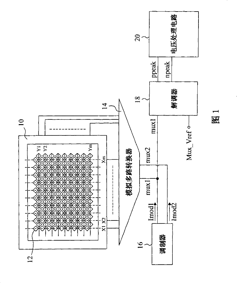
[0063] figure 1It is a schematic diagram of an embodiment of the present invention. There are multiple sensors 12 on the capacitive touch panel 10. The vertical sensors 12 are connected by wires to form traces (trace) X1, X2...Xm, and the horizontal sensors 12 also form the trace lines Y1, Y2...Ym respectively, the current signal generated by the modulator 16 selects the trace to be connected to through the analog multiplexer 14, and modulates into signals mux1 and mux2, and the demodulator 18 uses the reference signal Mux_Vref The signal mux1 is demodulated to generate signals ppeak and npeak to the voltage processing circuit 20 , and the voltage processing circuit 20 converts the voltage difference between the signals ppeak and npeak to obtain capacitance change information on the capacitive touch panel 10 .

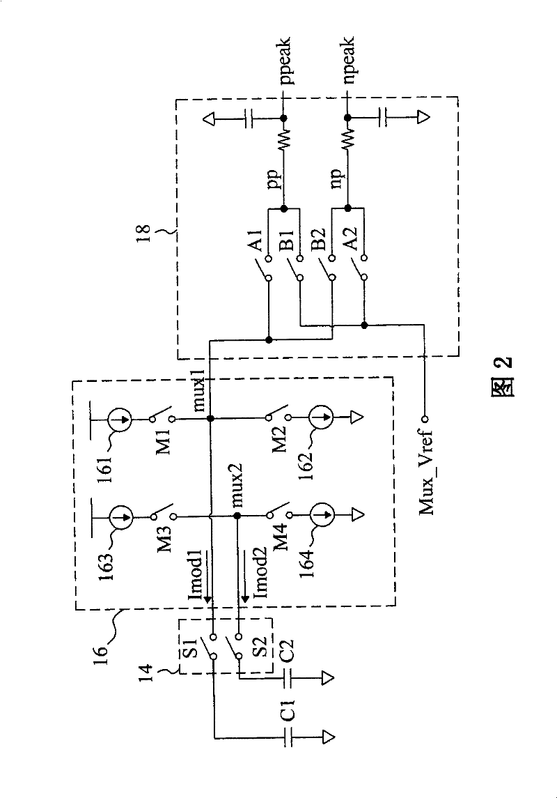
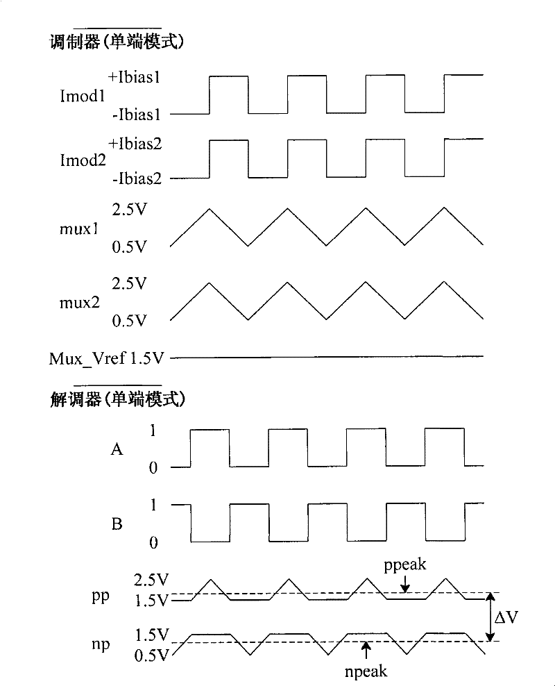
[0064] figure 2 for figure 1 The circuit diagram of the embodiment, image 3 The single-ended signal waveform diagrams in the modulator and demodulator are shown. ...


PUM


Abstract

The invention provides control circuit and method of a capacitance type touch control panel and a capacitance type touch control panel module. The control circuit comprises the following structure that: a modulator provides a first signal and a second signal which has the same phase with the first signal; a multiplexer is coupled with the capacitance type touch control panel and the modulator, provides the first signal to a first trace and provides the second signal to a second trace; and a demodulator is coupled with the multiplexer and demodulates the signal on the first trace by a reference signal. Each trace on the capacitance type touch control panel is charged and discharged by a scanning signal, and the signal of the adjacent trace of the trace or a lower grounding layer, which hasthe same phase with the scanning signal, is provided so as to lower the parasitic capacitance between the scanned trace and the grounding layer or other traces, thereby lowering the basic capacitanceof the capacitance type touch control panel, increasing the induction quantity of the control circuit, providing a shielding effect, lowering the noise interference and enhancing the efficacy of the capacitance type touch control panel.

Description

technical field [0001] The present invention relates to a capacitive touch panel, in particular to a control circuit, method and application of the capacitive touch panel. Background technique [0002] Capacitive touch panels are currently widely used in notebook computers, mobile phones, personal digital assistants, and multimedia playback panels because of their thinness, compactness, power saving, and durability. Capacitive touch panels are generally based on printed circuit boards, glass or plastic films, and metal, indium tin oxide conductive films or other material patterns are printed on them as sensors. According to different applications, the shape and shape of the sensors Size also varies. When a conductor such as a stylus or a finger touches the touchpad, it will cause a capacitance change on the sensor. The control circuit detects the capacitance change on the sensor to obtain the information input by the user, and then perform touch control. Therefore, In the ...

Claims


Application Information

Patent Timeline
Patent Type & Authority Patents(China)
IPC IPC(8): G06F3/044
Inventor 黄俊中王尊民林俊佑
Owner ELAN MICROELECTRONICS CORPORATION
Learn More