Plug wire device
A technology of inserting and leading wires, applied in the direction of pipes/pipe joints/pipes, cable laying equipment, mechanical equipment, etc., to prevent failures
- Summary
- Abstract
- Description
- Claims
- Application Information
AI Technical Summary
Problems solved by technology
Method used
Image

Examples
Embodiment 1
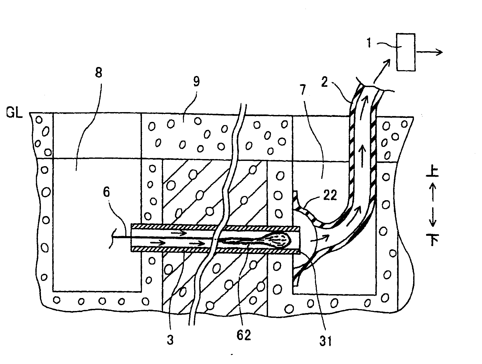
[0147] refer to figure 1 Example 1 will be described. figure 1 is a schematic cross-sectional view of the wire insertion device of this embodiment. The vacuum suction device 1 is driven by a motor. An air hose 2 made of a rubber tube or a resin tube is fixed so as to cover an opening on the suction side of the vacuum suction device 1 . The vacuum suction device 1 sucks air through an air hose 2 .
[0148] Pipelines 3 serving as cable laying pipes are buried under roads. A lead wire 6 consisting of a steel wire helix is inserted into the line 3 . Both ends of the pipeline 3 are connected to the side of the inspection hole 7 and the inspection hole 8 . The road surface 9 is provided on the surface of the road. The inspection holes 7 and 8 are provided at a predetermined distance, for example, about 200 meters along the road. The insertion port of the pipeline 3 buried in the ground is open toward the wall surface of the inspection hole 8 . The outlet portion 31 of the ...
Embodiment 2
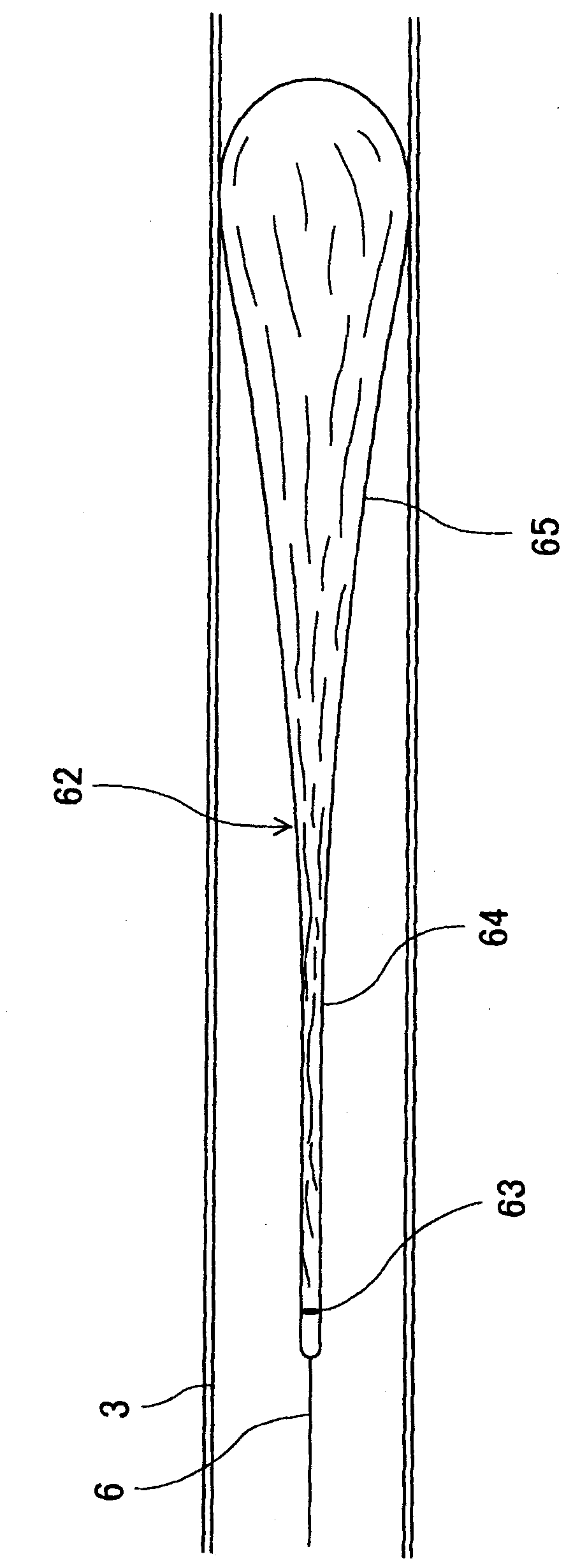
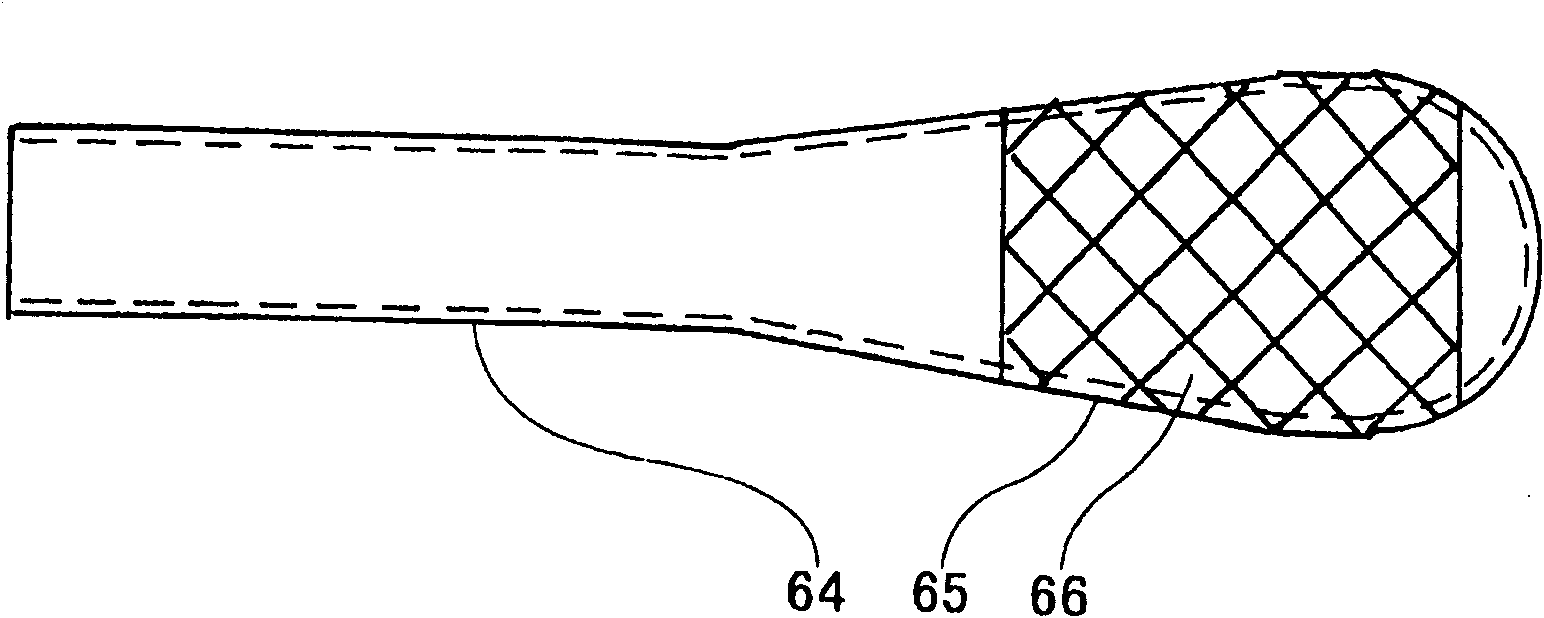
[0165] refer to Figure 6 Example 2 will be described. Figure 6 is a schematic side view of the sealed long bag 62. However, the sealed long bag 62 is subjected to a differential pressure in the pipeline 3 shown in the cross-sectional view. The airtight long bag 62 has a resin bag portion 625 made of a resin film capable of sealing air therein, and a reinforcement portion 626 having flexibility and higher tensile strength in the longitudinal direction than the resin bag portion 625 . The reinforcing part 626 is made of a resin mesh thicker than the resin film constituting the resin bag part 625 , and covers the resin bag 625 .
[0166] Figure 7 It is a partially enlarged schematic side view showing a part of the reinforcement part 626 enlarged. A rear end portion (not shown) of the reinforcement portion 626 is connected to a front end portion (not shown) of the lead wire 6 (not shown) together with a rear end portion (not shown) of the resin bag portion 625 .
Embodiment 3
[0168] Embodiment 3 will be described with reference to 8. FIG. Figure 8 It is a radial cross-sectional schematic view of the sealed long bag 62 . The sealed long bag 62 has a resin bag portion 625 and a reinforcement portion 626 joined to each other. The resin bag portion 625 is a sealed bag made of a resin film. The reinforcing part 626 is composed of a resin band 6261 having a higher strength than the resin bag part 625 .
[0169] Figure 9 express Figure 8 Modification of the sealed long bag shown. A plurality of short resin bands 6261 are dispersedly arranged on the surface of the resin bag portion 625 .
PUM
 Abstract
Description
Claims
Application Information
 - R&D
- Intellectual Property
- Life Sciences
- Materials
- Tech Scout
- Unparalleled Data Quality
- Higher Quality Content
- 60% Fewer Hallucinations
Browse by: Latest US Patents, China's latest patents, Technical Efficacy Thesaurus, Application Domain, Technology Topic, Popular Technical Reports.
© 2025 PatSnap. All rights reserved.Legal|Privacy policy|Modern Slavery Act Transparency Statement|Sitemap|About US| Contact US: help@patsnap.com