Image processing apparatus

An image processing device and image technology, which can be used in image communication, carrier pointing device, television, etc., and can solve problems such as reducing operability

Inactive Publication Date: 2011-03-30
SANYO ELECTRIC CO LTD
View PDF6 Cites 0 Cited by
  • Summary
  • Abstract
  • Description
  • Claims
  • Application Information

AI Technical Summary

Problems solved by technology

[0004] However, when the angle of view (aspect ratio) differs between the image recorded on the cassette tape and the imag

Method used


Image

  • Image processing apparatus
  • Image processing apparatus
  • Image processing apparatus

Examples


Embodiment 1

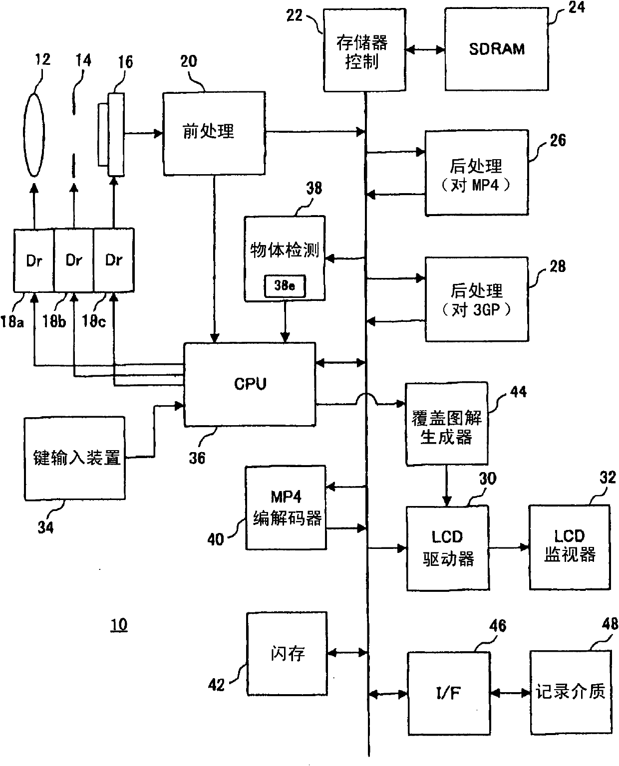
[0064] refer to figure 2 , the digital video camera 10 of this embodiment includes: a focusing lens 12 and an aperture unit 14 driven by drivers 18a and 18b, respectively. The optical image of the subject scene is irradiated onto the imaging surface of the image sensor 16 through these members. In addition, the effective image area of ​​the imaging plane has a resolution of 2560 pixels horizontally x 1600 pixels vertically.

[0065] When the power is turned on, the CPU 34 activates the driver 18c in order to execute the moving image reading process at the start of imaging. The driver 18c exposes the imaging surface in response to the vertical synchronization signal Vsync generated every 1 / 60 second, and reads the charges generated on the imaging surface in a sequential scanning state. Raw image data representing the subject scene is output from the image sensor 16 at a frame rate of 60 fps.

[0066] The pre-processing unit 20 performs processing such as digital clamping, p...

Embodiment 2

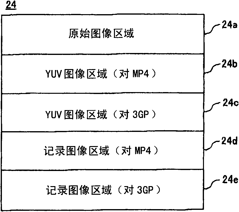
[0120] and figure 2 The difference between the embodiments is that the digital video camera 10 of other embodiments such as Figure 22 As shown, the post-processing circuit 28 used for the 3GP file is omitted, such as Figure 23 The YUV image area 24c for 3GP files is shown omitted. Additionally, by Figure 22 The CPU36 shown executes the Figure 24 camera work and Figure 25 The cut control job 1, at the following point with Figure 10 The camera work shown and Figure 12 The cut control job 1 shown is different.

[0121] exist Figure 24 In step S105, among the MP4 file and the 3GP file, only the MP4 file is created and opened. In addition, in step S107, the MP4 codec 40 and the I / F 46 are activated in order to start the recording process. Then, the MP4 codec 40 stops at writing the compressed image data based on the image data of the 1080 / 60i system stored in the YUV image area 24b into the recording image area 24d. The I / F 46 also stops at writing the compressed...


PUM


Abstract

The invention provides an image processing apparatus. A pre-treatment circuit (20) reads an original image data output from an image sensor (16). A post-treatment circuit (26) creates the image data corresponding to a cut-out area (CT1) allocated to the scene, based on the read original image data. The post-treatment circuit (28) creates the image data corresponding to the cut-out area (CT2) having a size that falls below a size of the cut-out area (CT1) and being allocated to the scene, based on the read original image. An LCD monitor (32) displays a capturing image as the image data based on the post-treatment circuit (26) so as to superpose a reference line (GL1) representing a position of the cut-out area (CT2) on the capturing image, thereby restraining low operation caused by different viewing angles between the image data as the post-treatment circuit (26) and the image data as the post-treatment circuit (28).

Description

technical field [0001] The present invention relates to an image processing device, and in particular to an image processing device suitable for use in a digital video camera for creating a plurality of photographed scenes representing a common photographed scene. Background technique [0002] An example of such a device has been disclosed in Patent Document 1. According to this background art, a video signal output from a camera unit is recorded on a tape cassette by a first compression method, and is recorded on a memory card by a second compression method. The video based on the video signal output from the camera unit is displayed on the LCD monitor. [0003] [Patent Document 1] Japanese Patent Laid-Open No. 2005-109923 [0004] However, when the viewing angle (aspect ratio) differs between the video recorded on the cassette tape and the video recorded on the memory card, an object appearing in one video disappears from the other video, thereby reducing operability. ...

Claims


Application Information

Patent Timeline
IPC IPC(8): H04N5/77G11B27/034G11B27/34
Inventor 藤田日出人
Owner SANYO ELECTRIC CO LTD
Why Eureka
Try Eureka