
Template of injection molding machine

A molding machine and template technology, which is applied in the field of injection molding machine templates, can solve the problems of template and mold service life, failure to guarantee product qualification, and lower product qualification rate, etc., to improve motion controllability, increase service life, and improve The effect of pass rate

Active Publication Date: 2011-04-06
GUANGZHOU HUAYAN PRECISION MACHINERY
View PDF6 Cites 5 Cited by
  • Summary
  • Abstract
  • Description
  • Claims
  • Application Information

AI Technical Summary

Problems solved by technology

The disadvantage of this type of structure is that the clamping force transmitted by the machine hinge to the mold will finally act on the two ends of the template and the mold, resulting in large bending deformation of the template and mold after being stressed, which will cause flash defects in plastic products. At the same time, it also has a great impact on the service life of the template and the mold; when using a mold with poor rigidity (such as a PET preform mold), the above-mentioned defects are particularly prominent, and it is even impossible to guarantee that the product is qualified, which seriously affects the life of the mold and reduces the quality of the finished product. pass rate, and increased production costs

Method used


Image

  • Template of injection molding machine
  • Template of injection molding machine
  • Template of injection molding machine

Examples


Embodiment Construction

[0024] In the following, the template of the injection molding machine of the present invention will be further described in conjunction with the accompanying drawings and specific embodiments, so as to understand the technical idea claimed by the present invention more clearly.

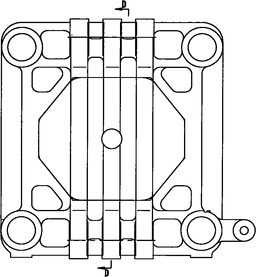
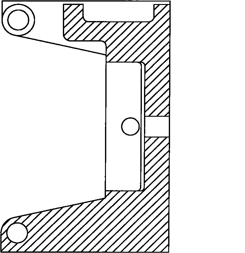
[0025] Such as image 3 , 4 , 5, 6, and 7 show a template for an injection molding machine of the present invention (the X direction in the figure describes the width direction of the injection molding machine template, and the Z direction describes its height direction), the main body is a cuboid structure, which includes a code Template 1, the code template is provided with a plurality of mounting holes for the installation and connection of the mold; on the code template 1, there is a flange 8 continuously arranged along its periphery, and the upper top surface of the flange 8 protrudes from the back surface of the code template 1 , thereby increasing the edge thickness of the code template 1 and...


PUM


Abstract

The invention relates to a template of an injection molding machine. The template comprises at least a code template for the installation of a mold, an upper hinged support and a lower hinged support which are positioned on the back surface of the template and guide holders distributed at four corners of the code template, wherein the circumference of the back surface of the code template is provided with a flange protruded from the surface, the back surface of the code template is provided with a continuous and closed back rib, and the guide holders are connected on the back rib; a diagonal rib forming an included angle with the code template is connected between the upper and lower hinged supports and the code template; a back plate is connected between the upper hinged support and the lower hinged support; and the transverse stressing area of the template is located in the middle part of the template, so that a longitudinal mold clamping force can be transferred to the middle part of the mold by the upper hinged support and the lower hinged support, thereby greatly improving the stressing conditions of the template and the mold, reducing or avoiding the flexural deformation of the template and the mold, prolonging the service life of the template and the mold, improving the qualification rate of the product, enhancing the movement controllability of the template and being beneficial to realizing high-precision mold protection. At the same time, the invention ensures that the template is rigid enough and fewer materials are consumed.

Description

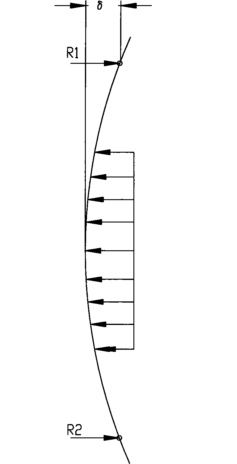
technical field [0001] The invention relates to an accessory of an injection molding machine, in particular to a template of an injection molding machine. Background technique [0002] In industrial production, injection molding is mostly used to make plastic products with a certain shape. [0003] In the existing injection molding machines, the mold clamping mechanism is used to provide mold clamping force and ejection force for the mold. The existing mechanical hinged mold clamping system is mainly composed of a fixed platen, a movable platen, a tail plate, a hinge and a guide column. The formwork is an important part of the clamping mechanism, and its deformation directly affects the plastic product. Quality and mold life. [0004] At present, in the hinged mold clamping system, the movable platen is usually designed as Figure 1a , 1b The horizontal "U"-shaped structure shown is to meet the assembly and force requirements of the mechanism. The force conditions are as ...

Claims


Application Information

Patent Timeline
Patent Type & Authority Applications(China)
IPC IPC(8): B29C45/66
Inventor 刘伟波阮长柏
Owner GUANGZHOU HUAYAN PRECISION MACHINERY
Learn More