
Method for controlling motion of vehicle and motion controller of vehicle

a technology of motion control and vehicle, which is applied in the direction of vessel construction, steering initiation, instruments, etc., can solve the problems of delicate uncomfortable feeling applied to steering feeling, heavy steering operation, and affecting the operation of steering wheel, so as to improve the motion controllability of the vehicle and ensure the operation. the effect of accuracy

Inactive Publication Date: 2005-10-27
TOYODA MASCH WORKS LTD
View PDF12 Cites 5 Cited by
  • Summary
  • Abstract
  • Description
  • Claims
  • Application Information

AI Technical Summary

Benefits of technology

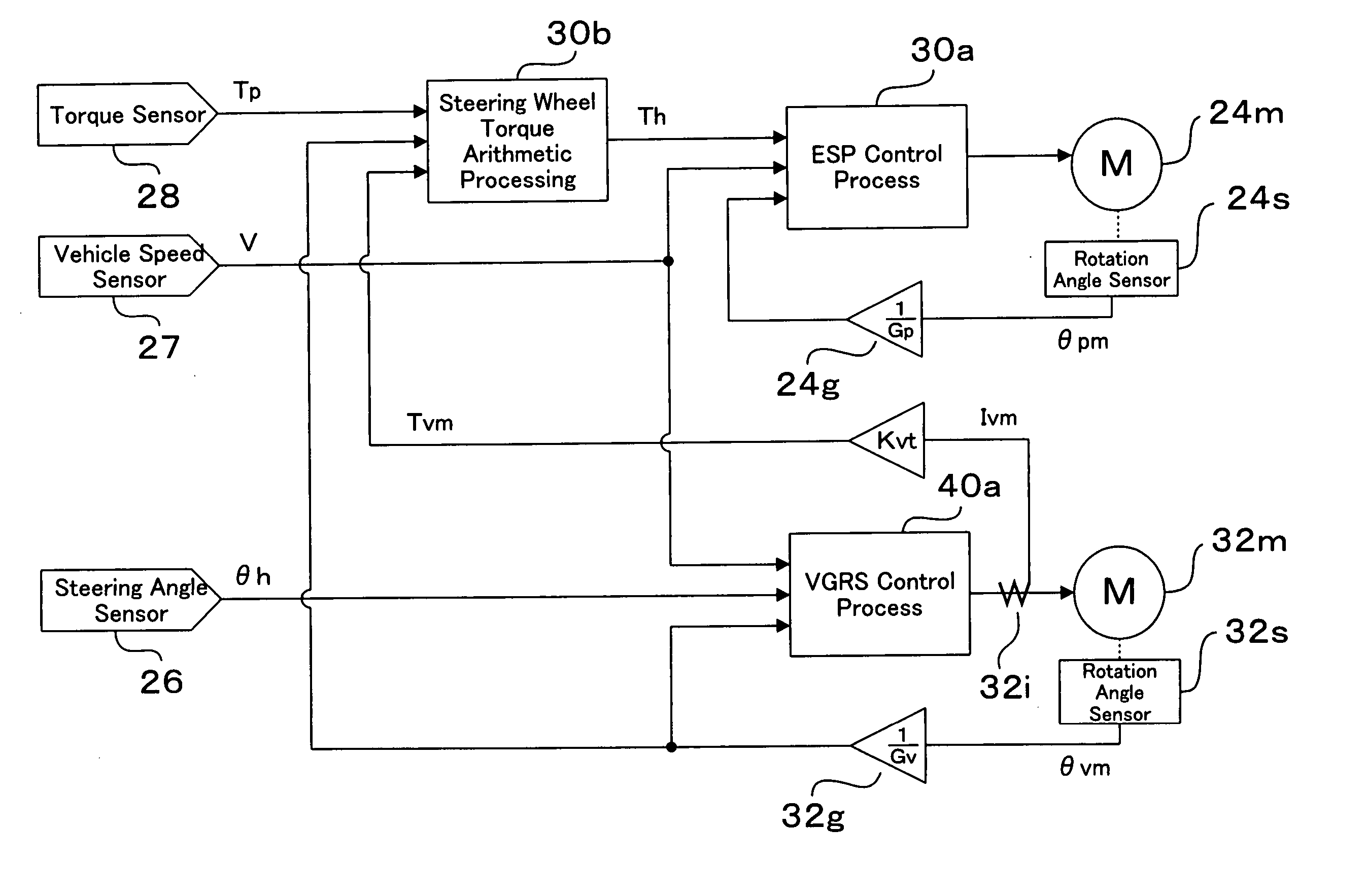
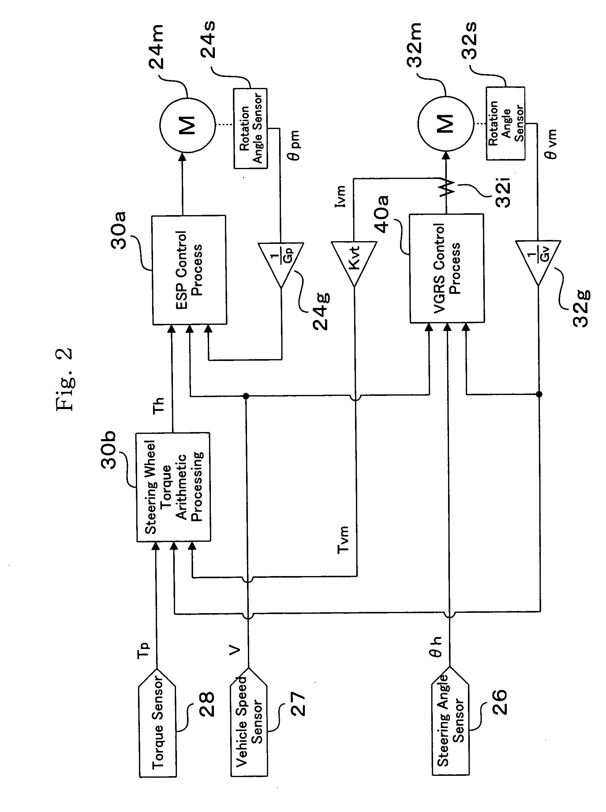
[0014] For example, in the case that the dynamic equation is constituted by the following formula (1), a steering wheel torque Th can be determined by using a steering torque Tp generated in the output shaft of the transfer ratio variable mechanism, a motor torque Tvm generated by a motor of the transfer ratio variable mechanism and a rotation angle θvm of the motor. Accordingly, the steering wheel torque can be known without adding any new torque sensor or the like. Therefore, the steering wheel torque Th can be determined in accordance with an arithmetic processing by means of a control computer, by detecting the steering torque Tp generated in the output shaft of the transfer ratio variable mechanism by means of an existing torque sensor, and detecting the motor torque Tvm and the motor rotation angle θvm by means of existing rotation angle sensor and current sensor which are used for controlling the motor. Accordingly, it is possible to improve a motion controllability of the vehicle without increasing the number of the parts. Th−Tp+Tvm=Jvm×d2θvm / dt2+Rvm×sign(dθvm / dt)   (1)
[0018] In accordance with a second aspect and a fourth aspect of the present invention, the steering wheel torque is determined by using at least one term of an inertia term of the transfer ratio variable mechanism and a Coulomb friction term of the transfer ratio variable mechanism, in configuration terms of the dynamic equation expressing the torque transfer by the transfer ratio variable mechanism. For example, in the case that the dynamic equation is constituted by the formula (1) mentioned above, the steering wheel torque is determined by using at least one term of the inertia term (a term of Jvm) of the transfer ratio variable mechanism constituting a right side first term of the formula (1) and the Coulomb friction term (a term of Rvm) of the transfer ratio variable mechanism constituting a right side second term of the formula (1). Accordingly, in the first aspect and the third aspect, the steering wheel torque is determined by employing a measured value or a design value for at least one term of the Jvm and Rvm set to the constant numbers. Therefore, it is possible to i an accuracy of operation of the arithmetic processing of determining the steering wheel torque Th. Accordingly, it is possible to further improve the motion controllability of the vehicle without increasing the number of the parts.

Problems solved by technology

Consequently, the steering operation becomes heavy and even if the steering wheel is turned largely, it canes that the steered wheels are steered a little.
In the case that the torque detected by the torque sensor 28 is used as a steering torque for controlling an EPS actuator 24, there is a problem that a delicate uncomfortable feeling can be applied to a steering feeling on the basis of a slight mismatch which may be generated between the driver's steering feeling and an actual steering.
However, since it is necessary to arrange the torque sensor independently from the torque sensor 28 of the second steering shaft 23, there is generated a new problem that an increase in a number of the parts and an increase in a manufacturing cost are caused.

Method used


Image

  • Method for controlling motion of vehicle and motion controller of vehicle
  • Method for controlling motion of vehicle and motion controller of vehicle
  • Method for controlling motion of vehicle and motion controller of vehicle

Examples


Embodiment Construction

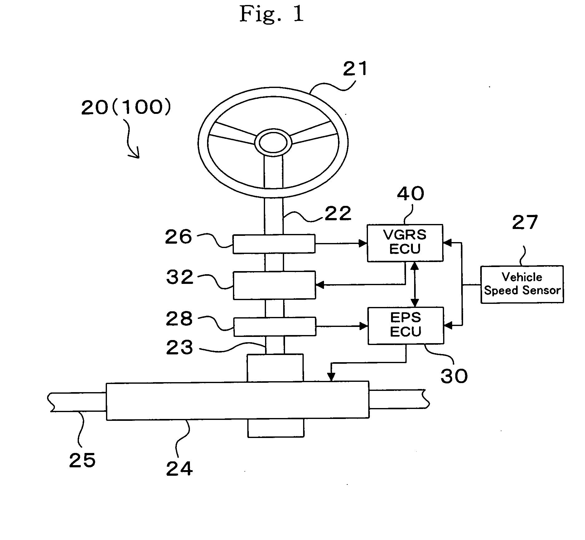
[0022] Hereinafter, the embodiment of the vehicle motion control apparatus which the vehicle motion control method and vehicle motion control apparatus of the present invention will be described with reference to the accompanying drawings. Meanwhile, because the vehicle motion control apparatus 20 of this embodiment is not different from the vehicle motion control apparatus 100 in terms of medical structure, the vehicle motion control apparatus 20 (100) shown in FIG. 1 will be described.

[0023] As shown in FIG. 1, a vehicle motion control apparatus 20 comprises a steering wheel 21, a first steering shaft 22, a second steering shaft 23, an EPS actuator 24, rods 25, a steering angle sensor 26, a vehicle velocity sensor 27, a torque sensor 28, an EPS_ECU 30, a gear ratio changing mechanism 32, a VGRS_ECU 40 and the like. Since mechanical and electrical connections of a vehicle motion control apparatus have been already described, description thereof is omitted here and the characters r...


PUM


Abstract

In accordance with a vehicle motion control apparatus, a steering wheel torque (Th) generated in accordance with an operation of a steering wheel is determined in accordance with a steering wheel torque arithmetic process (30b) by EPS_ECU by using a steering torque (Tp) generated in a second steering shaft of a gear ratio variable mechanism, a motor torque (Tvm) generated by a motor (32m) of the gear ratio variable mechanism and a rotation angle (θvm) of the motor (32m), on the basis of a dynamic equation expressing a torque transfer by the gear ratio variable mechanic Accordingly, even in the case that the vehicle motion control apparatus employs a structure that the gear ratio variable mechanism is interposed between the steering wheel and a torque sensor, the steering wheel torque (Th) can be known without adding any new torque sensor or the like. Therefore, it is possible to improve a motion controllability of the vehicle without increasing a number of parts by using the steering wheel torque (Th) for an ESP control process (30a).

Description

CROSS-REFERENCE TO RELATED APPLICATIONS [0001] The present application claims priority under 35 U.S.C. § 119 to Japanese Patent Application No. JP 2002-126768. The contents of these applications are incorporated herein by reference. TECHNICAL FIELD [0002] The present invention relates to motion control method of vehicle and motion control apparatus of vehicle. BACKGROUND ART [0003] As a vehicle motion control apparatus including a transmission ratio changing mechanism for changing the transmission ratio by driving a motor, provided halfway of a steering transmission system which connects a steering wheel to steered wheels, a vehicle motion control apparatus 100 which comprises a steering wheel 21, a first steering shaft 22, a second steering shaft 23, an EPS actuator 24, rods 25, a steering angle sensor 26, a vehicle velocity sensor 27, a torque sensor 28, an EPS_ECU 30, a gear ratio changing mechanism 32, a VGRS_ECU 40 and the like, as shown in FIG. 1, is available. In the meantime...

Claims


Application Information

Patent Timeline
IPC IPC(8): B62D5/00B62D5/04B62D5/22B62D6/00B62D101/00B62D113/00B62D119/00
CPCB62D5/008B62D6/008B62D5/0463
Inventor KATO, HIROAKIMOMIYAMA, MINEKAZUYASUI, YOSHIYUKITANAKA, WATARUASANO, KENJIIMOTO, YUZUOONO, EIICHIMURAGISHI, YUJI
Owner TOYODA MASCH WORKS LTD
Learn More