

Collection motor for drawing machine
A plotter and servo motor technology, applied in the field of plotter motors, can solve problems such as low work efficiency, and achieve the effects of easy control, accurate paper delivery, and power reduction
Inactive Publication Date: 2011-04-06
CHANGZHOU SINAJET SCI & TECH
View PDF0 Cites 1 Cited by
- Summary
- Abstract
- Description
- Claims
- Application Information
AI Technical Summary
Problems solved by technology
[0003] In order to overcome the deficiency of low working efficiency of the existing paper reel motor, the present invention provides a paper reel motor for plotters
Method used
View moreImage
Smart ImageViewing Examples


Examples
Embodiment Construction
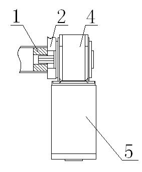
[0010] Such as figure 1 It is a structural schematic diagram of the present invention, a paper delivery motor for a plotter, including a delivery rod 1 and a mounting plate 2, the paper delivery rod 1 is connected with a worm gear reducer 4 through the mounting plate 2, and the worm gear The reducer 4 is connected to the servo motor 5 .
[0011] Now a servo motor with deceleration is used, which reduces the power of the paper receiving motor and reduces the noise. Through servo control, the paper receiving is more accurate and the transmission is more stable. The worm gear and worm have the function of reverse self-locking, so that The drawn graphics are more precise and easier to control.
Login to View More PUM
 Abstract
The invention relates to the technical field of a motor for a drawing machine, in particular to a collection motor for a drawing machine. The collection motor comprises a collection rod and an installing plate, wherein the collection rod is connected with a worm gear speed reducer through the installing plate, and the worm gear speed reducer is connected with a servo motor. By adopting the servo motor with speed reduction, the invention lowers the power of the collection motor and the noise; according to the servo control, the invention enables the collection to be more accurate and the transmission to be more stable; and the worm gear has a reverse self-locking function, so that the drawn pattern is more accurate and can be controlled more easily.
Description
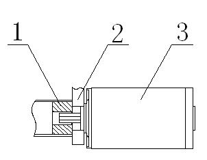
technical field [0001] The invention relates to the technical field of plotter motors, in particular to a paper delivery motor for plotters. Background technique [0002] Most of the paper receiving motors of plotters use high-power stepping motors. The existing paper receiving motors such as figure 1 As mentioned above, the paper reel 1 is connected to the stepping motor 3 through the mounting plate 2. This structure cannot be used flexibly in the actual operation process, and the noise is relatively large, which reduces the work efficiency. Contents of the invention [0003] In order to overcome the disadvantage of low working efficiency of the existing paper receiving machine motor, the invention provides a paper receiving motor for plotters. [0004] The technical solution adopted by the present invention to solve the technical problem is: a paper delivery motor for a plotter, including a delivery rod and a mounting plate, the paper delivery rod is connected with a wo...
Claims
Login to View More Application Information
Patent Timeline
 Patent Type & AuthorityApplications(China)
IPC IPC(8): B65H18/10H02K7/10
Inventor涂杰
OwnerCHANGZHOU SINAJET SCI & TECH