Construction machine, in particular paver or movable feeder

A technology of construction machinery and building materials, applied in the direction of construction, roads, roads, etc., can solve problems such as uneven surface of new roads, truck drivers stepping on the brakes, etc.

Inactive Publication Date: 2011-04-06
DYNAPAC
View PDF9 Cites 0 Cited by
  • Summary
  • Abstract
  • Description
  • Claims
  • Application Information

AI Technical Summary

Problems solved by technology

Also, it can happen that the truck driver hits the brakes so that the paver can no longer propel the tr

Method used


Image

  • Construction machine, in particular paver or movable feeder
  • Construction machine, in particular paver or movable feeder
  • Construction machine, in particular paver or movable feeder

Examples


Embodiment Construction

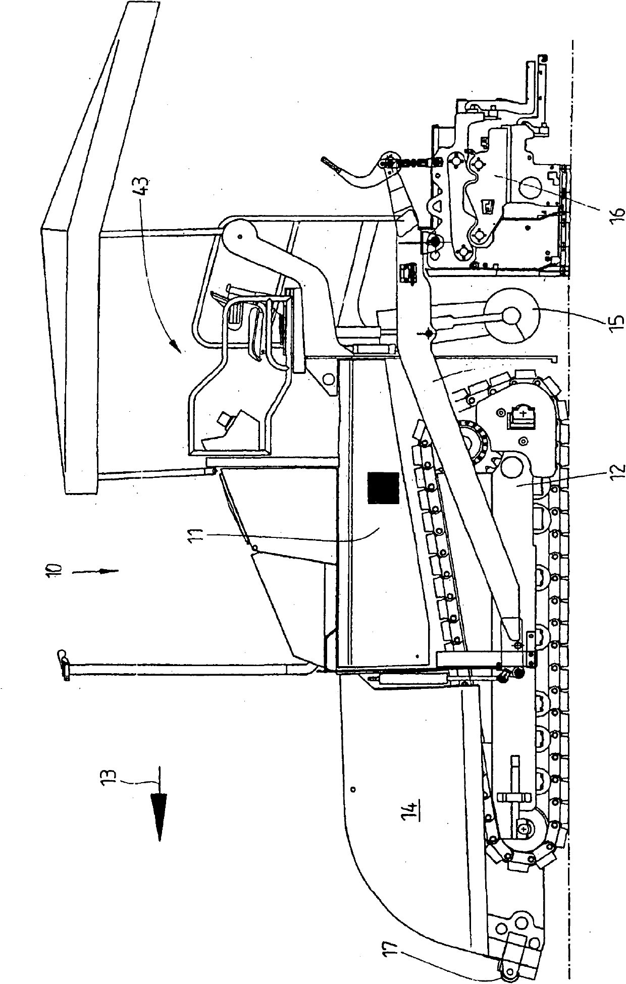
[0025] figure 1 A paving machine 10 schematically shown in FIG. 2 is used to create a road surface. In this respect, they can be any type of road surface.

[0026] Paving machine 10 is constructed to be self-propelled. For this purpose, it has a central drive unit 11 which has, for example, an internal combustion engine including a hydraulic pump for supplying the hydraulic motor and optionally a generator for generating energy for the electric drive.

[0027] Furthermore, the road paver 10 has a travel mechanism 12 which, in the illustrated embodiment, is constructed as a track gear laying mechanism. However, the carriage 12 of the paving machine can also be a wheeled carriage. The travel mechanism 12 is driven by a drive unit so that the road paver 10 can be moved forward in the production direction 13 .

[0028] Viewed in the production direction 13 , the storage bin 14 , which is configured in the form of a trough or hollow, is arranged in front of the drive unit 11 . ...


PUM


Abstract

The invention relates to a construction machine, comprising a drivable chassis (12) capable of being driven, at least one storage container (14) for the road construction material and a thrust roller (17) mounted on the front of the storage container (14) on the drivable chassis (12), characterized in that: the construction machine also comprises at least one thrust device for damping thrust exerted on the thrust rollers.

Description

technical field [0001] The invention relates to a construction machine according to the preamble of claims 1 , 7 and / or 13 . Background technique [0002] Paving machines and mobile feeders are used to generate road surfaces, which are made, for example, of asphalt, but also of other road building materials, such as concrete. The road building material to be processed is transported to the job site by truck and then dumped directly into the storage hopper of the paving machine or the storage hopper of the mobile feeder which conveys the material to the paving machine. During the forward motion of a self-propelled paving machine or mobile feeder, road building material is dumped from the truck into the storage hopper of the road paver or mobile feeder. At the same time, the paver or mobile feeder pushes the truck forward. [0003] To push the truck forward, the paving machine and the mobile feeder comprise push rollers at their ends which are located at the front in the pro...

Claims


Application Information

Patent Timeline
IPC IPC(8): E01C19/12
CPCE01C19/48E01C2301/08
Inventor M·勒曼H·布拉默
Owner DYNAPAC
Why Eureka
Try Eureka