Refrigerator handle assembling structure capable of realizing self-locking

An assembly structure and self-locking technology, which is applied to the spherical handle of the wing fan, the building lock, the wing fan handle, etc., can solve the problems of complicated procedures, improve the assembly efficiency, the assembly operation is simple and convenient, and the overall appearance effect is improved.

Active Publication Date: 2011-04-06
HISENSE HOME APPLIANCES GRP CO LTD +1
View PDF5 Cites 8 Cited by
  • Summary
  • Abstract
  • Description
  • Claims
  • Application Information

AI Technical Summary

Problems solved by technology

[0005] The technical problem to be solved by the present invention is to overcome the shortcomings of existing refrigerator handles that must be fixed by screws and complicated procedures, and provide a refrigerator handle assembly structure with self-locking mechanism, convenient operation and high production efficiency

Method used


Image

  • Refrigerator handle assembling structure capable of realizing self-locking
  • Refrigerator handle assembling structure capable of realizing self-locking
  • Refrigerator handle assembling structure capable of realizing self-locking

Examples


example 1

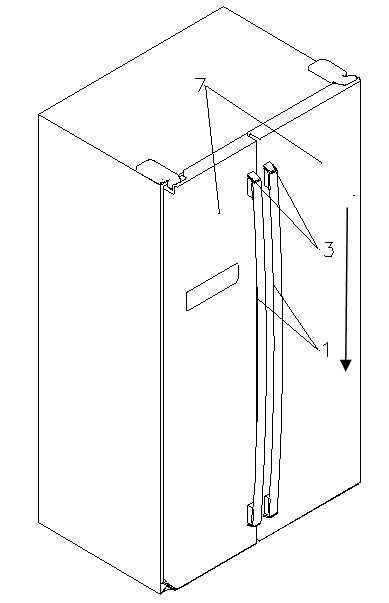
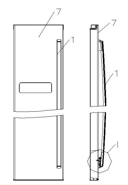
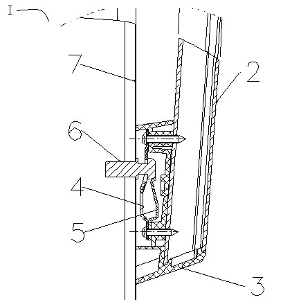
[0032] see figure 1 , figure 2 , image 3 , Figure 4 , the self-locking refrigerator handle assembly structure of the present invention includes a handle part 1, a handle 2, a handle seat 3, a handle connecting block 4, a self-locking elastic piece 5, a handle pillar 6 and a foam refrigerator door body 7. The handle support 6 is fixed on the refrigerator door 7, and the handle part 1 is buckled onto the handle support 6. The handle part 1 includes the handle 2 and the set handle seat 3 at the upper and lower ends of the handle 2, and the handle seat 3 is equipped with a handle connecting block 4 and the self-locking shrapnel 5, one end of the handle connection block 4, one end of the self-locking shrapnel 5 and one end of the handle base 3 are fixed on the handle 2 through the first connecting piece, the other end of the handle connection block 4 and the other end of the handle base 3 One end is fixed to the handle 2 through the second connecting piece; the other end ...

example 2

[0048] Such as Figure 7 Shown handle connection block 4 with Figure 8 The self-locking shrapnel 5 shown can also be designed as a whole, such as Figure 11 As shown, the material is made of spring steel, formed by a sheet metal mold, and integrated Figure 7 Shown handle connection block 4 with Figure 8 All the functions and assembly principles of the self-locking shrapnel 5 shown are completely the same as the first embodiment.

[0049] The refrigerator handle installation process is as follows:

[0050] After the refrigerator door body 7 foams, it will be as Figure 9 The handle support 6 shown is assembled on the door body 7 of the foaming refrigerator through an air batch, and the assembly effect diagram is shown in Figure 10 shown;

[0051] will be like Figure 5 Aluminum alloy handle 2 shown as well as Figure 11 The integral handle connection block shown is screwed to the Image 6 On the handle seat 3 shown, form the handle part 1, such as Fig...


PUM


Abstract

The invention relates to a refrigerator handle assembling structure capable of realizing self-locking, comprising a handle member and a handle strut fixed on a refrigerator door body. The handle strut is fixed to the refrigerator door body; the handle member is fastened onto the handle strut; the handle member comprises a handle and handle bases arranged at the upper and the lower ends of the handle; each handle base is internally provided with a handle connection block and a self-locking elastic sheet; one end of each handle connection block, one end of each self-locking elastic sheet and one end of the corresponding handle base are fixed on the handle through a first connector; the other end of each handle connection block and the other end of the corresponding handle base are fixed on the handle through a second connector; a locking plate slope for dead locking of the handle strut is arranged at the tail end of the other end of each self-locking elastic sheet; and each handle connection block is provided with a chute in which the handle strut slides. The invention achieves the final fixing effect by the dead locking of the handle member through the self-locking elastic sheets fixed in the handle bases and overcomes the defects of macroscopic irregularity, cockamamie operation, and the like caused by fixing the handle member with screws in the prior art.

Description

technical field [0001] The invention relates to the technical field of refrigerators in electrical equipment, in particular to a refrigerator handle assembly structure capable of realizing self-locking. Background technique [0002] At present, most refrigerator handles are made of aluminum alloy extrusions in the middle, and plastic handle fixing seats are designed at both ends. The handle fixing seats and aluminum alloy pull rods are assembled into handle parts. The connection block or the handle fixing column is connected with the foam door body, and then the final fixing is completed by screws. [0003] At present, this kind of handle assembly structure uses screws to complete the final fixation, which is cumbersome to operate, and the fixing screw can only be handled by adding a screw cover or directly exposing it within the visible range, whether it is adding a screw cover or directly exposing the screw All have a great influence on the appearance effect of the handle...

Claims


Application Information

Patent Timeline
Patent Type & Authority Applications(China)
IPC IPC(8): E05B1/00F25D23/02
Inventor 李春雷五八郭相凡
Owner HISENSE HOME APPLIANCES GRP CO LTD
Why Eureka
Try Eureka