Intelligent drawer type reactive compensation device with compensation function and special shipping car
A compensation device, intelligent technology, applied in reactive power compensation, reactive power adjustment/elimination/compensation, switchgear, etc., can solve maintenance difficulties, no compensation device is provided to assemble or disassemble maintenance auxiliary equipment, harmonic current burns Problems such as bad components to achieve the effect of high power factor
- Summary
- Abstract
- Description
- Claims
- Application Information
AI Technical Summary
Problems solved by technology
Method used
Image
Examples
specific Embodiment approach 1
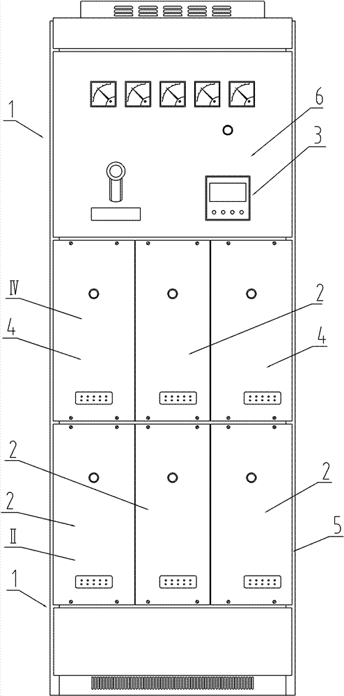
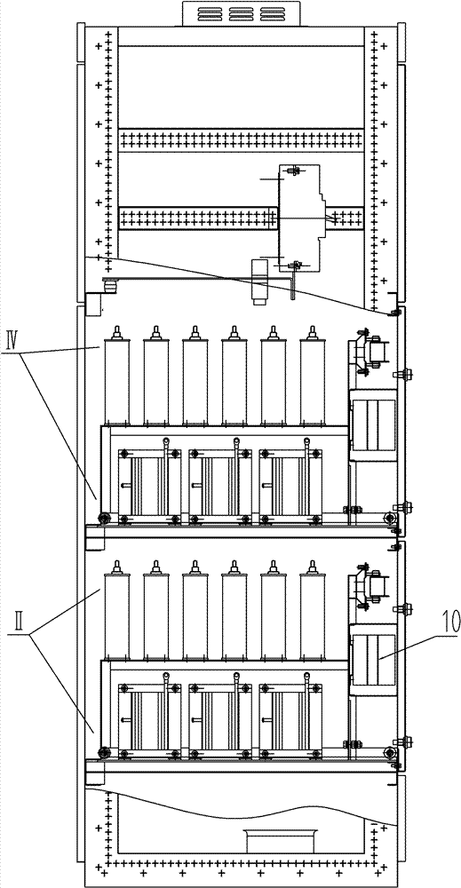
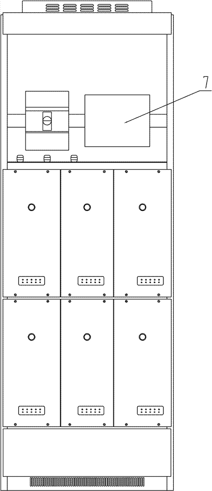
[0011] Specific implementation mode one: as Figure 1-13 As shown, the intelligent drawer-type reactive power compensation device with the compensation function described in this embodiment includes a compensation cabinet 1, a controller 3, a plurality of main compensation single-group compensator units II, and multiple compensation single-group compensator units IV, the reactive power compensation device also includes multiple main compensation single-group compensation drawer housings 2, multiple compensation single-group compensation drawer housings 4, and the multiple main compensation single-group compensation drawer housings 2 and multiple compensation The single-group compensating drawer housings 4 are all orderly and drawably installed at the corresponding positions in the compensating cabinet body 1, and corresponding drawer tracks are arranged in the compensating cabinet body 1, and the multiple main compensating single-group compensating drawer housings Body 2, mult...
specific Embodiment approach 2
[0015] Specific implementation mode two: as Figure 1~6 As shown, the main compensation single-group compensation drawer housing 2 and the compensation single-group compensation drawer housing 4 in this embodiment both include a drawer panel 8, a drawer pull-out booster mechanism 9, a drawer frame 13 and a travel pulley 16. The drawer panel 8 is installed on the front end of the drawer frame 13 , the travel pulley 16 is arranged on the bottom of the drawer frame 13 , and the drawer pull-out booster mechanism 9 is arranged on the bottom end of the drawer frame 13 and is close to the drawer panel 8 . Wherein the bottom beam rear end of drawer frame 13 protrudes from the frame rear column 5 millimeters, and this protruding part is specially used for inserting the gap between the receiving beam and the track rear beam, and the drawer can be pulled out and advanced easily on the drawer track. Other components and connections are the same as those in the first embodiment.
[0016] ...
specific Embodiment approach 3
[0017] Specific implementation mode three: as Figure 1-12As shown, the compensation cabinet 1 in this embodiment includes a cabinet frame main body 5, a single set of drawer rails 31, a receiving rail 32, a front beam 33 of a track, and a rear beam 34 of a track. , the front crossbeam 33 of the track and the rear crossbeam 34 of the track are all installed in the cabinet frame main body 5, the front crossbeam 33 of the track is placed on the front end of the single group of drawer tracks 31, and the rear crossbeam 34 of the track is placed at the rear end of the single group of drawer tracks 31. The rear end of the group drawer track 31 is designed with a slope of 15 degrees to connect with the receiving track 32, and there is a gap (5 mm) between the upper side of the receiving track 32 and the inner side of the upper side of the track rear crossbeam 34 for the protruding part of the drawer frame 13 to be inserted and locked. for. Other compositions and connections are the ...
PUM
 Abstract
Description
Claims
Application Information
 - R&D
- Intellectual Property
- Life Sciences
- Materials
- Tech Scout
- Unparalleled Data Quality
- Higher Quality Content
- 60% Fewer Hallucinations
Browse by: Latest US Patents, China's latest patents, Technical Efficacy Thesaurus, Application Domain, Technology Topic, Popular Technical Reports.
© 2025 PatSnap. All rights reserved.Legal|Privacy policy|Modern Slavery Act Transparency Statement|Sitemap|About US| Contact US: help@patsnap.com


