Large asynchronous motor rotor fanning strip lamination structure

A technology for asynchronous motors and segments, which is applied in the direction of magnetic circuit shape/style/structure, manufacturing stator/rotor body, magnetic circuit rotating parts, etc., and can solve the problems of lamination failure, screw bending, low efficiency of rotor segment assembly, etc. problems, to achieve the effect of improving reliability, simple structure, and reducing the difficulty of lamination

Active Publication Date: 2011-04-06
SEC ELECTRIC MACHINERY
View PDF5 Cites 15 Cited by
  • Summary
  • Abstract
  • Description
  • Claims
  • Application Information

AI Technical Summary

Problems solved by technology

The traditional structure of a large asynchronous motor uses a screw for positioning, and the gap between the screw and the screw hole is 0.1mm. This mechanism has the disadvantage of low work efficiency for the rotor sector piece set, and sometimes the screw is slightly bent and cannot be laminated after being stacked on top.

Method used


Image

  • Large asynchronous motor rotor fanning strip lamination structure
  • Large asynchronous motor rotor fanning strip lamination structure
  • Large asynchronous motor rotor fanning strip lamination structure

Examples


Embodiment Construction

[0013] The specific embodiments of the present invention will be further described below in conjunction with the accompanying drawings.

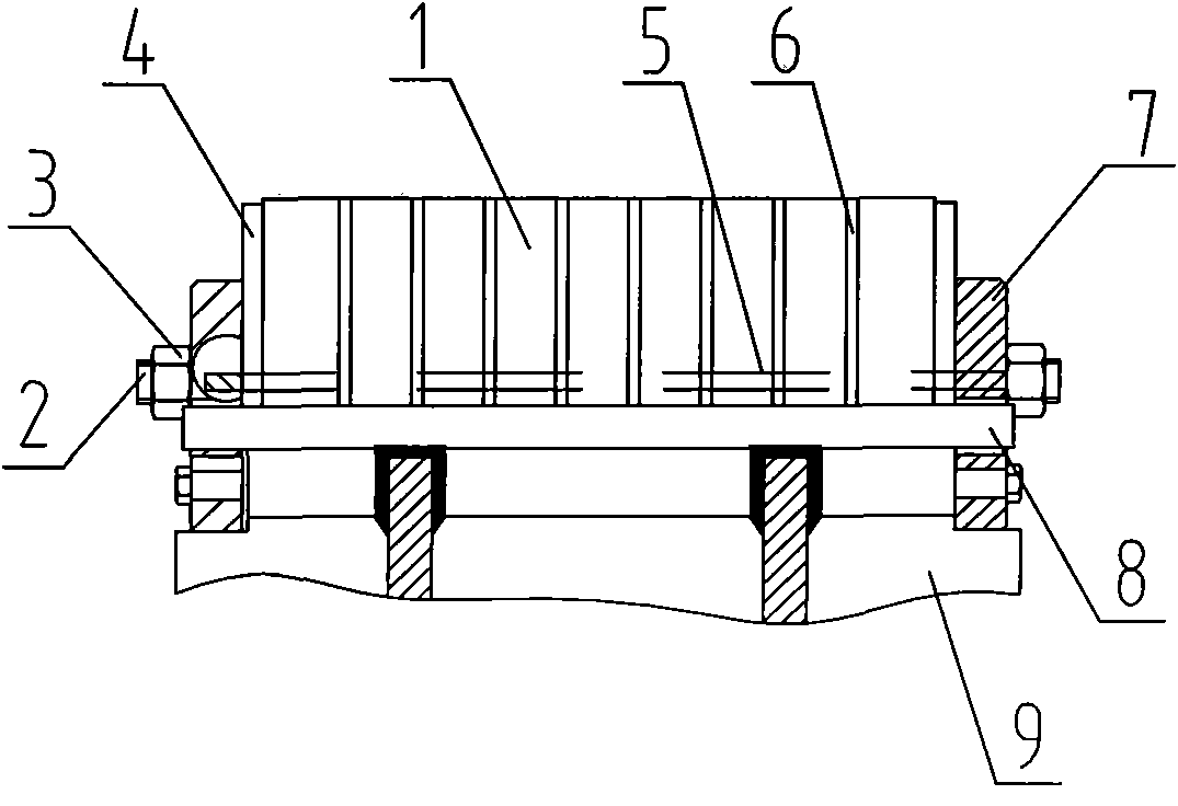
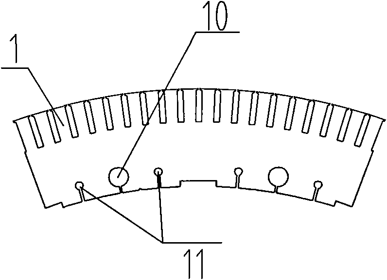
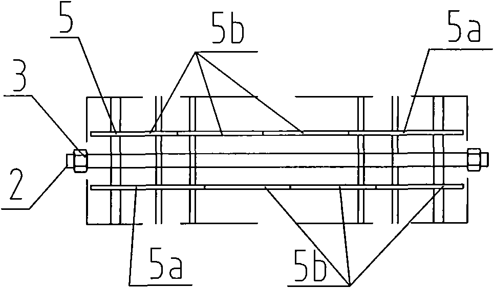
[0014] Such as figure 1 As shown, the present invention includes a rotor segment 1, a screw rod 2, a hex nut 3, a rotor end plate 4, a pin 5, a rotor ventilation groove plate 6, a rotor pressure ring 7, an oblique key 8 and a rotor bracket 9. The rotor pressure ring 7 is closed on the rotor bracket 9 . The rotor end plate 4 , the rotor ventilation slot plate 6 and the rotor segment 1 are positioned and laminated on the rotor bracket 9 and between the two rotor pressure rings 7 through the pin 5 . The screw rod 2 runs through the laminated rotor end plate 4 , the rotor ventilation slot plate 6 and the rotor sector piece 1 , and the hex nuts 3 are fastened to both ends of the screw rod 2 . The oblique key 8 fastens the structure between the two rotor pressure rings 7 as a whole.

[0015] The stacking process is as follows: first, put a roto...


PUM


Abstract

The invention relates to a large asynchronous motor rotor fanning strip lamination structure comprising a rotor fanning strip, a tie bolt, a stop pin, a rotor clamping ring, a rotor ventilation trough plate, a rotor end plate and an inclined key, wherein the rotor fanning strip, the rotor fanning ventilation trough plate and the rotor end plate are positioned by pins during the laminating process; and after the rotor fanning strip and the like are laminated, a screw tightly pulls the rotor fanning strip and the rotor clamping ring, and the inclined key is subject to thermal beating. Screw holes and pin holes are punched on the rotor fanning strip, the number of the pin holes is two times of that of the screw holes, a gap between each screw hole and the screw is 0.3-0.5 mm, and a gap between each pin hole and the pin is 0.1 mm. The invention has simple and compact structure and obvious acting effect; under the condition of not changing a structural material and ensuring qualified motor magnetic property characteristics, the laminating difficulty of the rotor fanning strip is lowered, and the reliability of the rotor is improved.

Description

technical field [0001] The invention relates to rotor segments, in particular to a laminated structure of large three-phase asynchronous motor rotor segments. Background technique [0002] For large asynchronous motors, when the rotor diameter exceeds 1200mm (or 1250mm). Due to the limitation of the width of the silicon steel sheet, the rotor core needs to be made into a fan-shaped lamination structure, and the stacked iron core forms a ring shape. When the rotor rotates, it needs to withstand the centrifugal force generated by the punch itself and the coil in the rotor core slot. The laminated core should maintain integrity and leave enough space between the rotor support (or welding shaft) for the transmission shaft. The amount of interference required for the friction torque between the rotor core and the rotor core. The traditional structure of a large asynchronous motor uses a screw for positioning, and the gap between the screw and the screw hole is 0.1mm. This mecha...

Claims


Application Information

Patent Timeline
Patent Type & Authority Applications(China)
IPC IPC(8): H02K1/32H02K15/02
Inventor 吕莹
Owner SEC ELECTRIC MACHINERY
Why Eureka
Try Eureka