Permanent magnet linear motor with clamping function

A technology of permanent magnet linear motor and linear motor, which is applied in the direction of electrical components, electromechanical devices, electric components, etc.

Inactive Publication Date: 2011-04-06
SOUTHEAST UNIV
View PDF6 Cites 4 Cited by
  • Summary
  • Abstract
  • Description
  • Claims
  • Application Information

AI Technical Summary

Problems solved by technology

The permanent magnet has a large suction force, so the force component is large, and it is difficult to obtain the ideal opening speed characteristics

Method used


Image

  • Permanent magnet linear motor with clamping function
  • Permanent magnet linear motor with clamping function

Examples


Embodiment Construction

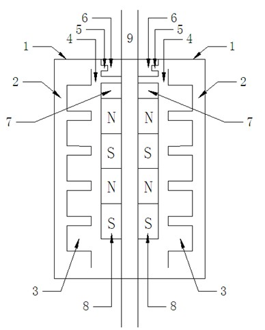
[0014] In the present invention, the permanent magnet 8 and the inner iron core 7 of the permanent magnet linear motor are fixed on the non-magnetic shaft 9 of the mover, the iron core 6 is fixed to the casing 1, and the coil 5 is wound on the teeth of the outer iron core 6 .

[0015] The linear motor includes a primary iron core 2, a primary coil 3, a permanent magnet 8, and a secondary nonmagnetic shaft 9. The primary iron core 2, primary coil 3, permanent magnet 8, and secondary nonmagnetic shaft 9 are arranged in sequence from outside to inside, The primary coil 3 is wound in the slot of the primary core 2, the non-magnetic shaft 9 supports the permanent magnet 8 and the inner core 7, and the air gap 4 is an air gap between the primary and the secondary , the inner iron core 7 is fixed on the secondary non-magnetic shaft 9 and is close to the upper end of the permanent magnet 8, and the outer iron core 6 is an iron core fixed on the casing 1; When the coil 5 is pulled in, ...


PUM


Abstract

The invention relates to a permanent magnet linear motor with a clamping function, comprising a primary core (2), a primary coil (3), a permanent magnet (8) and a secondary non-magnetic shaft (9) which are arranged from exterior to interior in sequence, wherein the primary coil (3) is wound in the slot of the primary iron core (2); the non-magnetic shaft (9) supports the permanent magnet (8) and an inner iron core (7); an air gap (4) is between the primary and the secondary; the inner iron core (7) is fixed on the secondary non-magnetic shaft (9) and tightly adhered to the upper end of the permanent magnet (8); an outer iron core (6) is fixed on a casing (1); a coil (5) is wound on the iron core (6); and in the case of suction, the suction on the iron core (7) is increased when the coil (5) is electrified to accelerate the suction and play the role in location, while in the case of disconnection, the coil (5) is reversely electrified to weaken axial magnetic field to accelerate the separation of a breaker.

Description

technical field [0001] The invention belongs to the field of linear motors, and is a cylindrical permanent magnet linear motor with a clamping function. This motor can be used in smart grids to undertake load allocation, accident prevention, especially large-area accident prevention, and maintenance of safe operation of the power grid. Background technique [0002] Intelligent high-voltage switchgear can improve the adaptive and self-healing capabilities of the power grid. Therefore, the intelligent high-voltage circuit breaker is an important development direction of high-voltage switchgear, and the key to its technology is to realize the safe and controllable operation of the operating mechanism. A high-quality operating mechanism requires a simple structure, few moving parts, and reliable operation to ensure that the circuit breaker can reliably achieve opening and closing operations. [0003] At present, the commonly used operating mechanisms of high-voltage circuit bre...

Claims


Application Information

Patent Timeline
Patent Type & Authority Applications(China)
IPC IPC(8): H02K41/02
Inventor 余海涛邓灿胡敏强
Owner SOUTHEAST UNIV
Why Eureka
Try Eureka