Electrostatic screen for an hvdct component

A high-voltage direct current, electrostatic shielding technology, applied in the direction of magnetic/electric field shielding, transformer/inductor parts, shielding materials, etc., can solve problems such as high cost and complicated use, achieve good contact, achieve matching, and reduce discharge time Effect

Active Publication Date: 2011-04-06
西门子能源全球两合公司
View PDF0 Cites 8 Cited by
  • Summary
  • Abstract
  • Description
  • Claims
  • Application Information

AI Technical Summary

Problems solved by technology

However, these measures are complex and costly to justify their use in p...

Method used


Image

  • Electrostatic screen for an hvdct component
  • Electrostatic screen for an hvdct component
  • Electrostatic screen for an hvdct component

Examples


Embodiment Construction

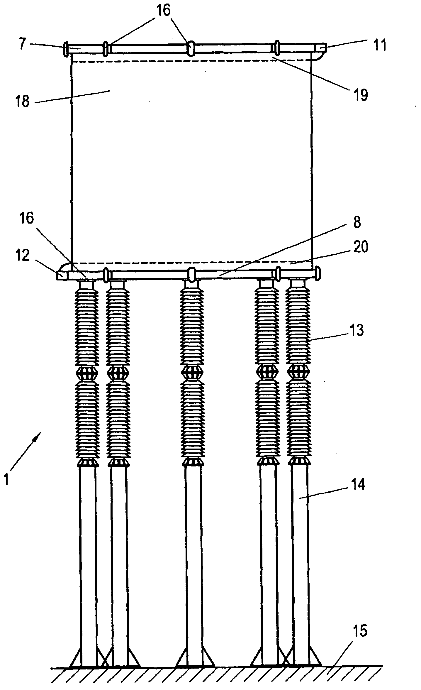
[0021] exist figure 1 with figure 2 shows a high-voltage direct current transmission air-core coil 1, which is for example in a high-voltage direct current transmission line is used as a filter choke.

[0022] Air core coils are "dry insulated" chokes, as opposed to oil insulated coils, where ambient air forms the external insulation of the choke, and air core coils generally also do not contain a ferromagnetic core.

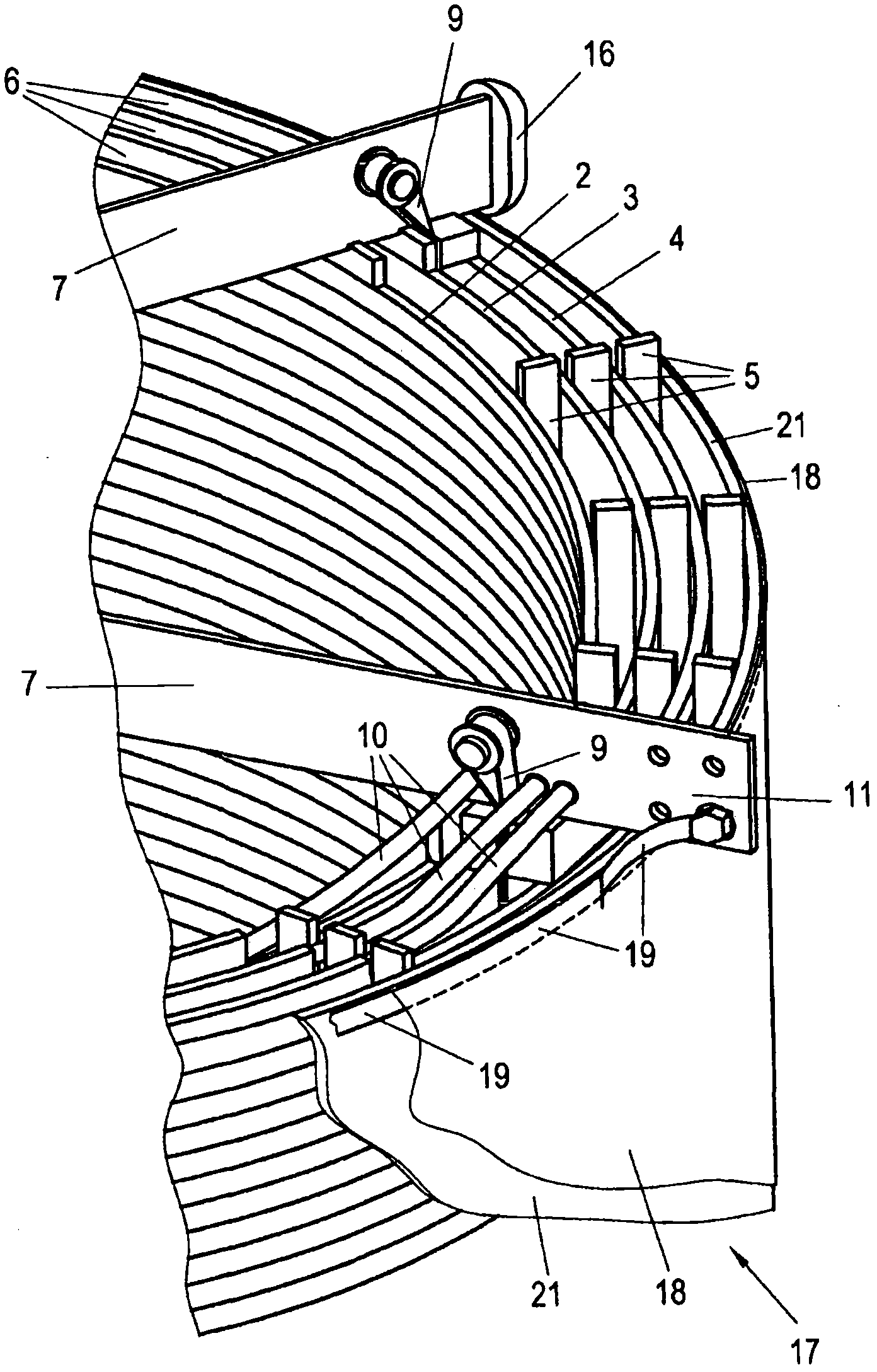
[0023] In the example shown, the air-core coil 1 has three concentric, electrically parallel winding layers 2 , 3 , 4 which are spaced apart from one another by spacers 5 in order to form cooling gaps 6 between them.

[0024] The winding layers 2 to 4 are fixed at their upper and lower ends by a collection of multi-arm star supports 7 , 8 which are braced against one another by means of tension straps 9 . The conductors of the winding layers 2 to 4 are electrically connected to the star carrier 7 , 8 and the star carrier has lugs which form the connections ...


PUM


Abstract

An electrostatic screen (17) for an HVDCT component (1), the connections (11, 12) of which are at a higher potential than earth (15) during operation, in particular for an HVDCT air-cored induction coil, is distinguished by a casing (18) which is provided at at least one end with a collector electrode (19, 20) which runs essentially over its circumference, for connection to one of the connections (11, 12) of the HVDCT component (1), wherein the casing (18) is manufactured from a sheet (22) of electrostatically dissipative material having a surface resistance in the range from 109 to 1014 ohm/units square.

Description

technical field [0001] The invention relates to a high-voltage direct current transmission component with at least two joints, especially an air-core coil for high-voltage direct current transmission ( - Electrostatic shielding of Luftdrosselspule). Background technique [0002] for HVDC transmission Parts that occur in areas that are at high potential (for example 500 to 800 kV) with respect to ground potential and are thus subject to continuous and sometimes strongly accumulated dirt at certain points, this is called "static collection Dust (electrostatic precipitation)" or "black spot (black spot)" phenomenon. The reason for this is the constant presence of charged particles in the air, such as ions, ionizable or polarizable dust particles and dirt particles, etc., which move towards the surface of the part in the strong electrostatic field between the part and its surroundings and deposited there. The degree of electrostatic fouling also depends on the amount of fr...

Claims


Application Information

Patent Timeline
IPC IPC(8): H01F27/34H05K9/00H01F27/36
CPCH01F37/005H01F27/343H05K9/0079H01F27/36H01F27/363H05K7/14339
Inventor H·赖辛格H·图马
Owner 西门子能源全球两合公司
Why Eureka
Try Eureka