
Cooling and humidifying type heat exchange device
A heat exchange device and wet-type technology, applied in heating methods, lighting and heating equipment, household heating, etc., can solve the problems of large power consumption, environmental pollution of refrigerants, and high cost, and achieve simple and reasonable structure and wide application range Wide range and high working efficiency
- Summary
- Abstract
- Description
- Claims
- Application Information
AI Technical Summary
Problems solved by technology
Method used
Image

Examples
Embodiment Construction
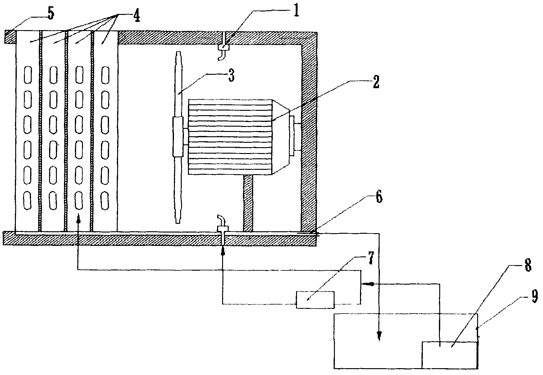
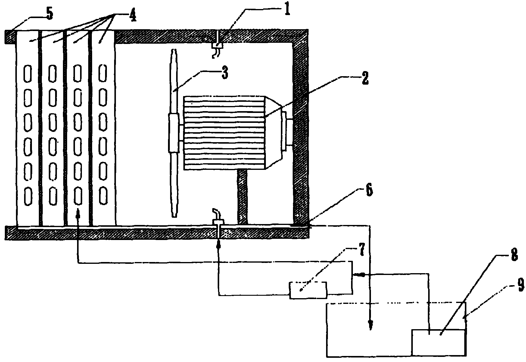
[0009] Embodiments of the present invention will be described in detail below in conjunction with the accompanying drawings. The cooling and humidifying heat exchange device includes a reservoir 9, a water pump 8 and a booster pump 7. The water pump 8 is arranged in the reservoir 9, and its water inlet is connected to the reservoir 9. The outlet of the water pump 8 is connected to the booster pump 7. The water inlet is connected, and the cooling capacity exchanger 4 and the fan 2 are sequentially installed inside the stainless steel tank body 5. The cooling capacity exchanger 4 is located at the notch of the stainless steel tank body 5, and the fan blade 3 is fixed on the fan 2 and faces the cooling capacity. The exchanger 4 is equipped with an atomizing nozzle 1 on the side wall of the stainless steel tank body 5, and a water collection tank 6 is arranged on the bottom of the stainless steel tank body 5. The water outlet of the booster pump 7 is connected with the atomizing no...
PUM
 Abstract
Description
Claims
Application Information