Electromagnetic wave conduction oil heater
A heat-conducting oil heater and electromagnetic wave technology, applied in heat storage heaters, fluid heaters, lighting and heating equipment, etc., can solve problems affecting the normal development of the industry, increase production costs, increase energy consumption, etc., and achieve heat conversion High efficiency, controlled heating temperature, and precise heating temperature effect
- Summary
- Abstract
- Description
- Claims
- Application Information
AI Technical Summary
Problems solved by technology
Method used
Image

Examples
Embodiment Construction
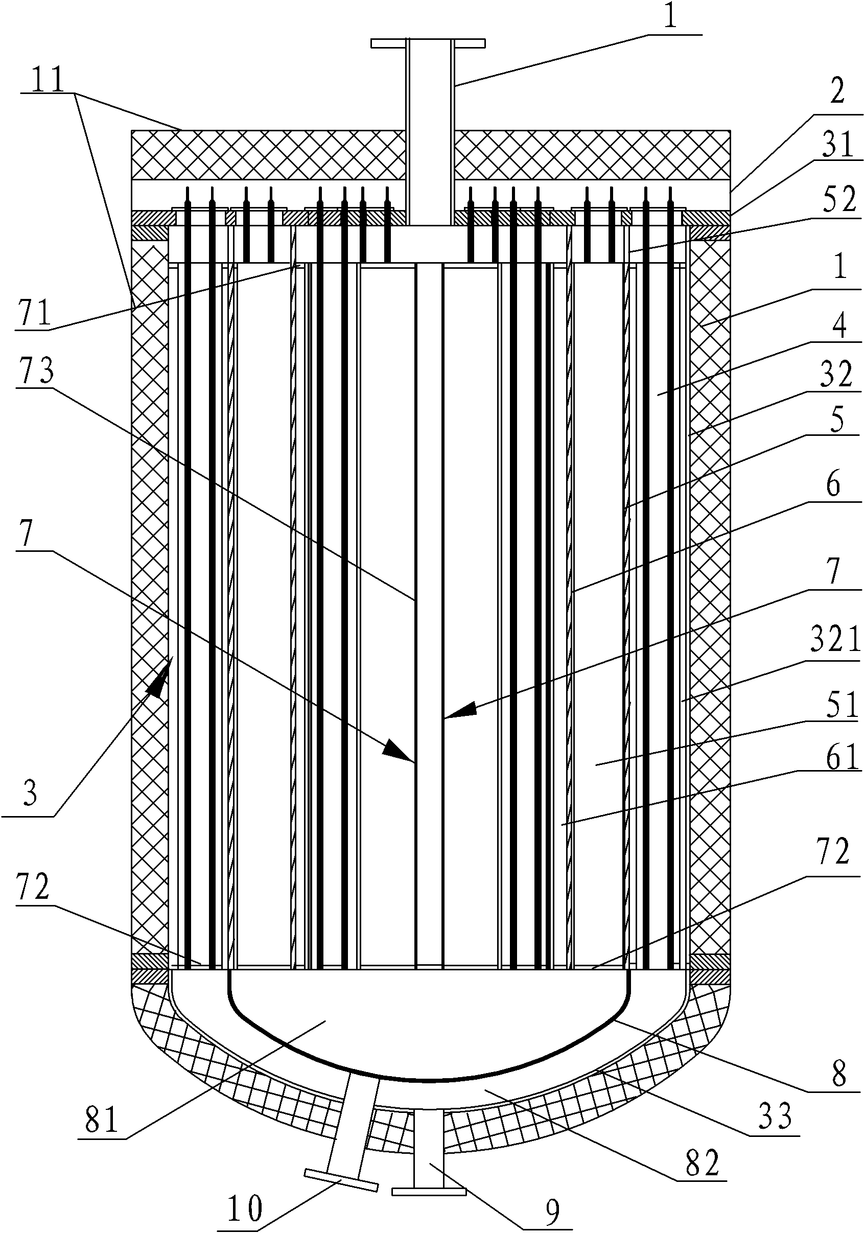
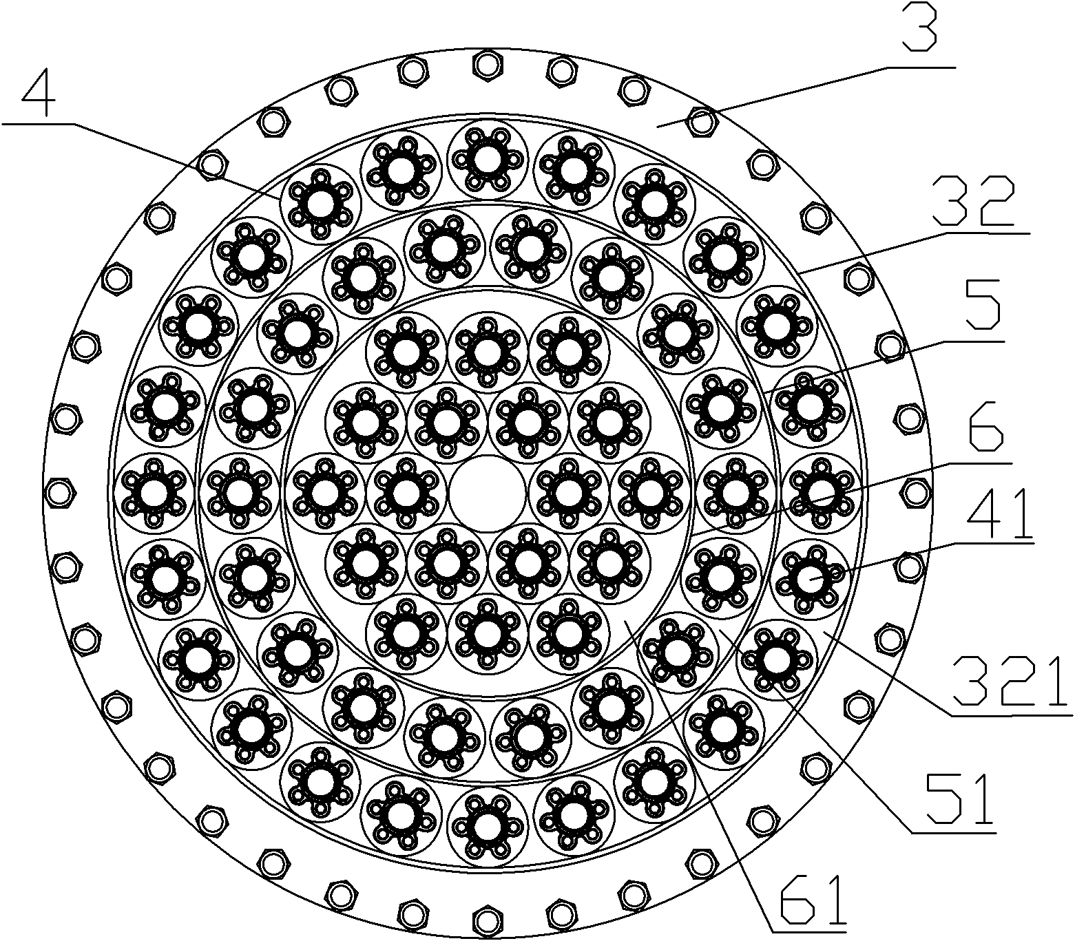
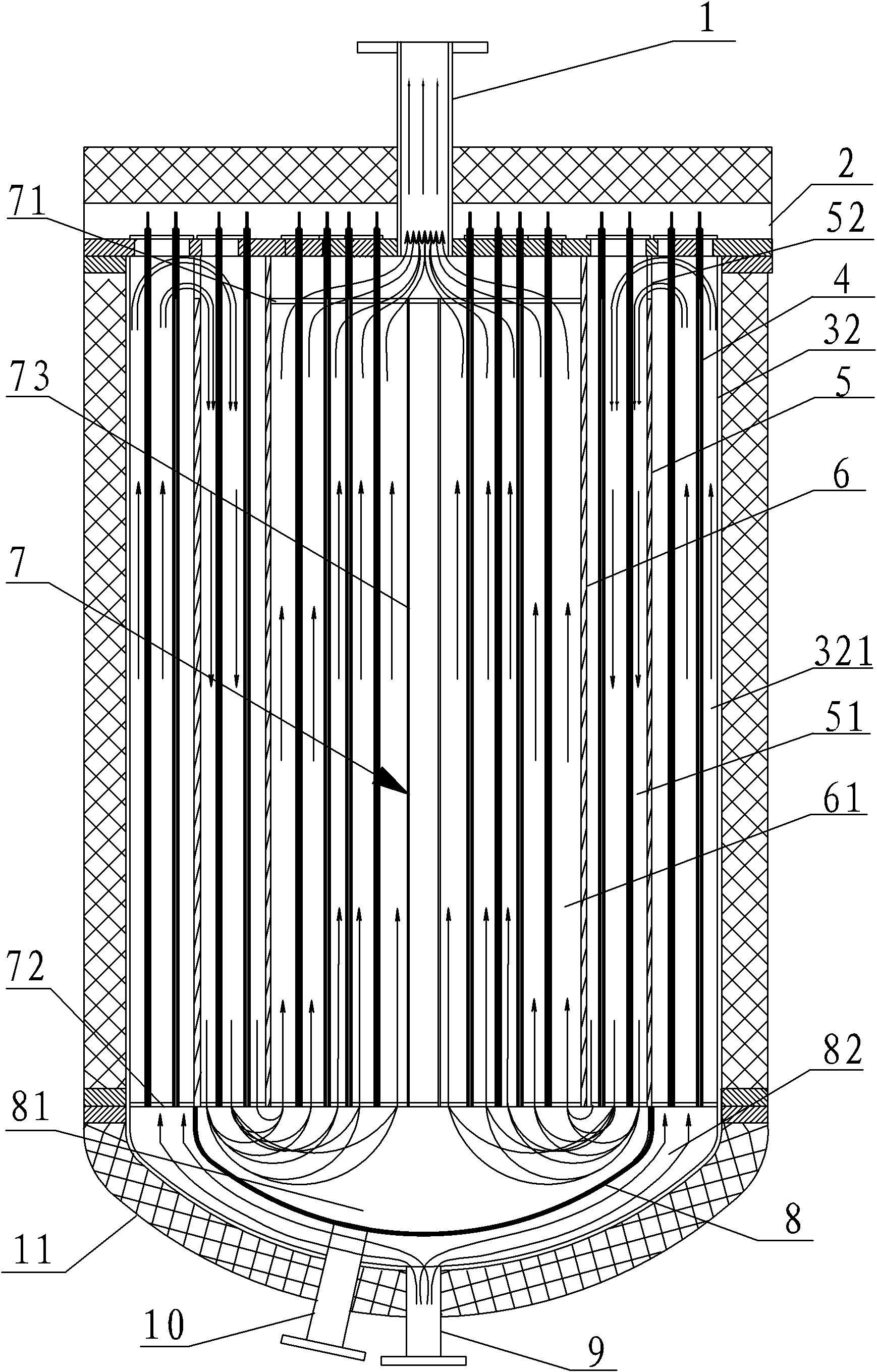
[0015] Figure 1 ~ Figure 3 It shows an electromagnetic wave heat conduction oil heater, which is characterized in that it is provided with a cylindrical shell 3, which is coaxially fixed with the cylindrical wall 32 and connected with the upper cover 31 of the shell, and has several overcurrents around the top circumference. The cylindrical middle partition 5 of the notch 52 and the cylindrical inner partition 6 that is sealingly connected with the upper cover of the casing, the middle partition 5 and the inner partition 6 extend to the bottom of the cylindrical wall to separate the inner space of the cylindrical wall An outer cavity 321, a middle cavity 51 and an inner cavity 61 are formed. In this example, there are 8 over-current gaps around the top circumference of the middle partition 5 . The outer cavity 321 and the middle cavity 51 are circular, and the inner cavity 61 is cylindrical; in the outer cavity, the middle cavity and the inner cavity, more than one layer of ...
PUM
 Abstract
Description
Claims
Application Information
PatSnap Eureka turns technology decisions into work you can execute. Powered by our Innovation Knowledge Graph, it runs expert workflows across engineering, life sciences, materials and intellectual property. Get your review-ready output in minutes.


