Self-rotating and cleaning device of dirt in heat transfer tube

A technology for cleaning devices and heat transfer tubes, which is applied in the directions of cleaning heat transfer devices, non-rotating equipment cleaning, lighting and heating equipment, etc. The effect of reduction, less fluid resistance, and improved durability

Inactive Publication Date: 2011-04-13
GUANGZHOU HUANGYAN ELECTRICAL & MECHANICAL TECH CO LTD
View PDF6 Cites 17 Cited by
  • Summary
  • Abstract
  • Description
  • Claims
  • Application Information

AI Technical Summary

Problems solved by technology

However, the heat exchangers in the above patents need to be specially made, and the size and clearance of the heat exchangers need to be relatively large; and there are three problems as follows: first, the brushes are installed in the shell side of the heat exchangers, making it difficult to replace the brushes and inconvenient to maintain
Secondly, the brush is installed in the flow field, and the water flow resistance increases, which affects the water flow; third, the transmission is hard-connected, and the equipment cost is high
The above three reasons make it difficult to promote the use of most projects in use

Method used


Image

  • Self-rotating and cleaning device of dirt in heat transfer tube
  • Self-rotating and cleaning device of dirt in heat transfer tube
  • Self-rotating and cleaning device of dirt in heat transfer tube

Examples


Embodiment Construction

[0018] Implementation example:

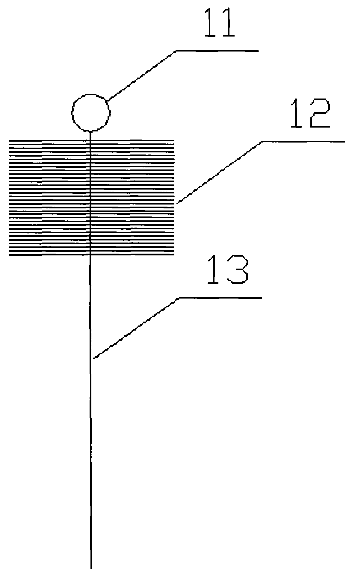
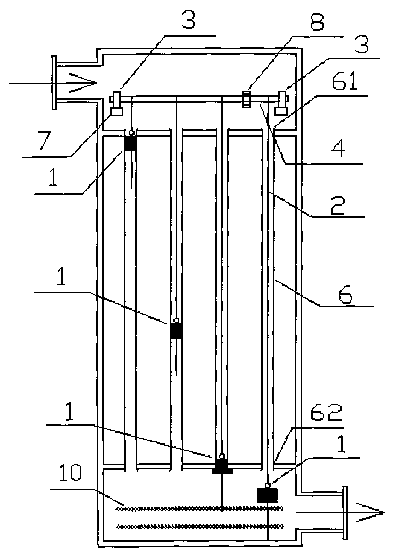
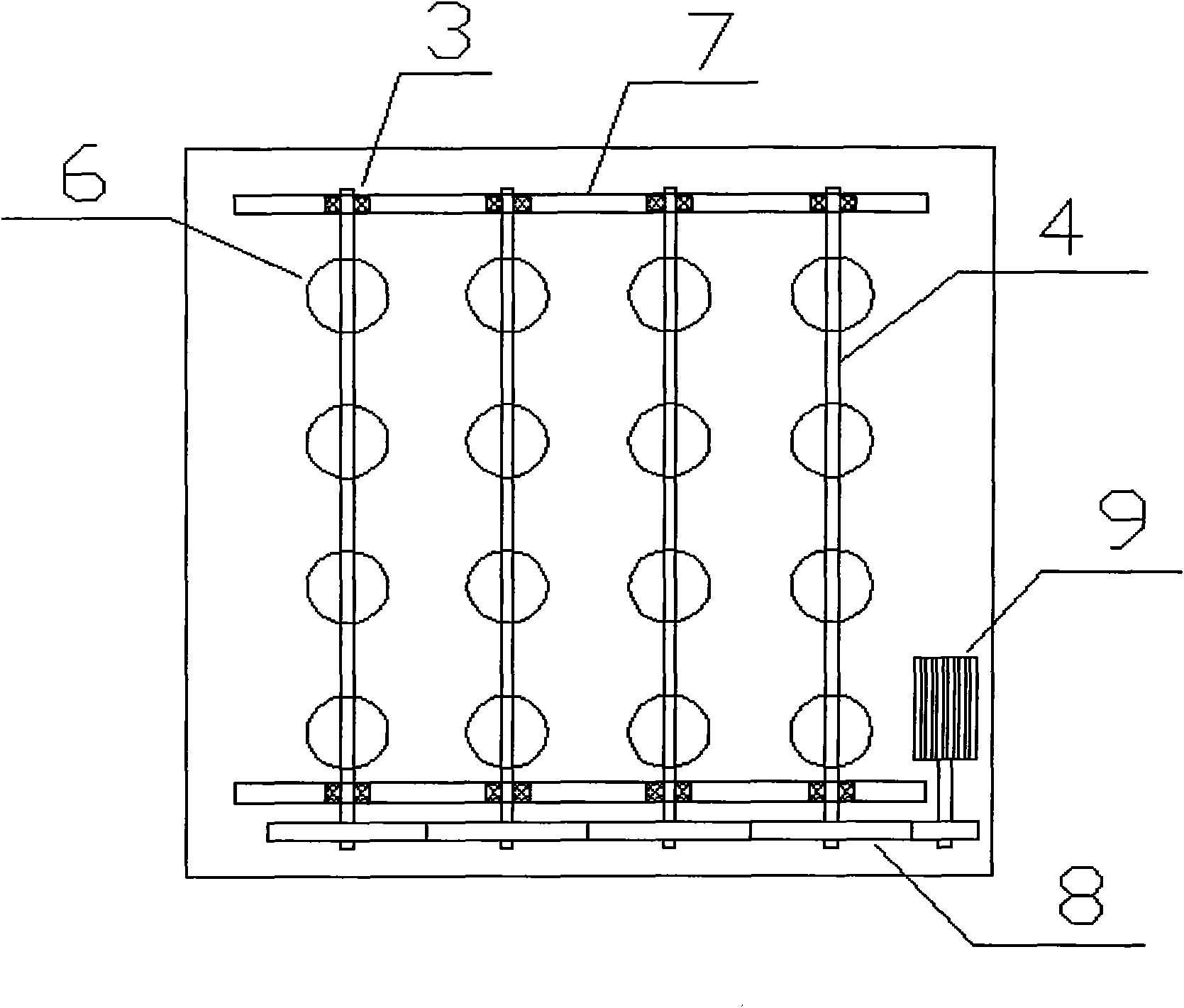
[0019] The structure diagram of the present invention is as figure 1 , 2 , shown in 3, including heat exchanger heat transfer tube 6, spiral brush 1, heat exchanger heat transfer tube 6 is provided with pipe inlet 61 and pipe outlet 62, and spiral hair brush 1 is placed in heat exchanger heat transfer tube 6, and can move linearly in the heat transfer tube 6 of the heat exchanger, and the spiral brush 1 can pass through the outlet 62 of the heat transfer tube 6 of the heat exchanger, and the spiral brush 1 is installed on the On the traction shaft 4, one end of the connecting rope 2 is connected to the spiral brush 1, and the other end of the connecting rope 2 passes through the inlet 61 of the heat transfer tube 6 of the heat exchanger and is fixed on the traction shaft 4, and the traction shaft 4 passes through the transmission mechanism 8 is connected with drive unit 9.

[0020] In this embodiment, the outer side of the pipe outlet 62 of ...


PUM


Abstract

The invention discloses a self-rotating and cleaning device of dirt in a heat transfer tube, comprising a spiral hairbrush arranged in the heat transfer tube of a heat exchange tube and can moves in a straight line in the tube, wherein the spiral hairbrush is arranged on a traction shaft by a connecting rope; one end of the connecting rope is connected with the spiral hairbrush; and the other end of the connecting rope passes through a pipe inlet of the heat transfer tube of the heat exchanger and is fixed on the traction shaft which is connected with a drive device through a driving mechanism. Scale attached to the wall of the heat transfer tube of the heat exchanger is removed under the action of friction and cleaning of the spiral hairbrush. In addition, when the self-rotating and cleaning device is free from cleaning, the spiral hairbrush has little influence on the fluid resistance and the flow change of the fluid can be correspondingly reduced by adopting a structure that the spiral hairbrush can be clamped on a dual-layer metal mesh away from an outlet of the heat transfer tube at a certain distance. In addition, the connecting rope is free from being stressed when not being for cleaning, so that the durability of the self-rotating and cleaning device can be greatly improved, the self-rotating and cleaning device can meet the requirement for operating for a long term and can be applied on general heat exchangers with the flow speed of the fluid being greater than 1m/s on a large scale.

Description

technical field [0001] The invention relates to a cleaning device inside a heat transfer tube, in particular to an automatic descaling device for a tube-and-tube heat exchanger, and belongs to the transformation technology of a self-cleaning device for dirt inside a heat transfer tube. Background technique [0002] Chinese Patent Publication Nos. CN101561232A and CN101216260A disclose two kinds of sewage heat exchangers. A brush driven by a mechanical guide rail is installed in the heat exchanger housing to clean and remove deposits adhering to the pipe wall. However, the heat exchangers in the above patents need to be specially made, and the size and clearance of the heat exchangers need to be large; and there are three problems as follows: first, the brushes are installed in the shell side of the heat exchangers, making it difficult to replace the brushes and inconvenient to maintain . Secondly, the brush is installed in the flow field, which increases the water flow resi...

Claims


Application Information

Patent Timeline
Patent Type & Authority Applications(China)
IPC IPC(8): F28G1/02F28G15/04
Inventor 洪元柏符学伍邹杰
Owner GUANGZHOU HUANGYAN ELECTRICAL & MECHANICAL TECH CO LTD
Why Eureka
Try Eureka