TFT-LCD (Thin Film Transistor-Liquid Crystal Display) drive circuit

A driving circuit and sub-circuit technology, applied in the direction of instruments, static indicators, etc., can solve the problems of not participating in the common electrode signal processing, affecting the screen display, TFT-LCD screen flickering, etc., to reduce the residual DC component and improve the screen display Effect, reduce screen flicker effect

Active Publication Date: 2011-04-13
BOE TECH GRP CO LTD +1
View PDF0 Cites 13 Cited by
  • Summary
  • Abstract
  • Description
  • Claims
  • Application Information

AI Technical Summary

Problems solved by technology

Although figure 2 The line used to represent the common electrode signal passes through the source drive circuit 2, but in fact each source drive sub-circuit in the source drive circuit does not participate in the processing of the common electrode signal
[0005] figure 2 The problem in the driving method shown in is that the voltages of the signals input on the electrodes for receiving the common electrode signals on the panel are the same. In fact, due to the different loads on the panel, different positions on the LCD panel need The voltage of the common electrode signal is different. For example, the common electrode signal required by the area covered by the data line driven by the first source drive subcircuit may be a 5.8 volt signal, and the data line covered by the second source drive subcircuit is responsible for driving The common electrode signal required by the area may be a 5.5-volt signal, and the common electrode signal required by the area covered by the data line driven by the third source driver sub-circuit may be a 5.3-volt signal
If the method in the prior art is adopted, the voltages of the signals input on each electrode for receiving the common electrode signal on the panel are all the same, which will cause the TFT-LCD screen to flicker (flicker), and will cause residual DC components (in the art Usually called residual DC) in the existence, affect the screen display

Method used


Image

  • TFT-LCD (Thin Film Transistor-Liquid Crystal Display) drive circuit
  • TFT-LCD (Thin Film Transistor-Liquid Crystal Display) drive circuit
  • TFT-LCD (Thin Film Transistor-Liquid Crystal Display) drive circuit

Examples


Embodiment Construction

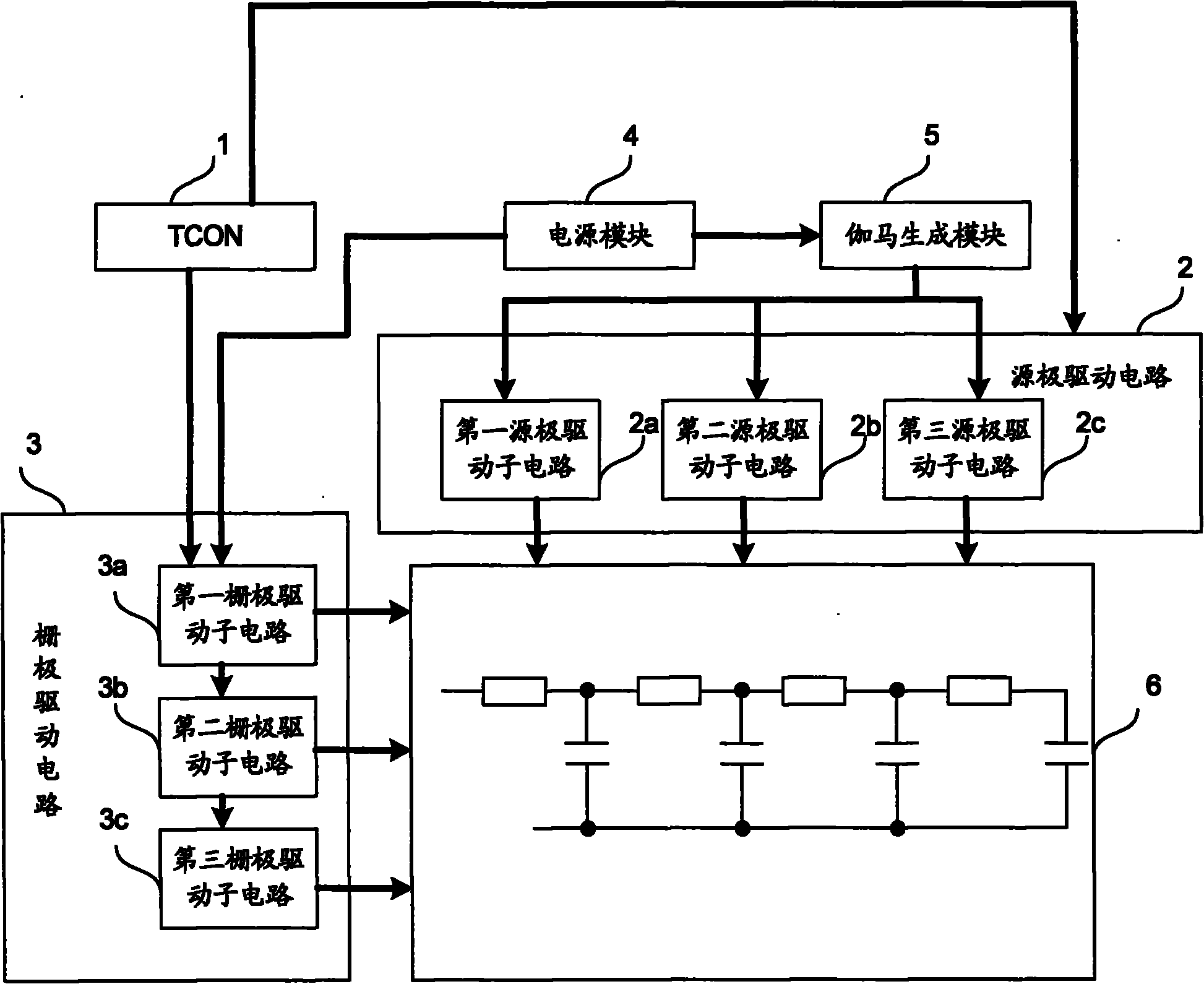
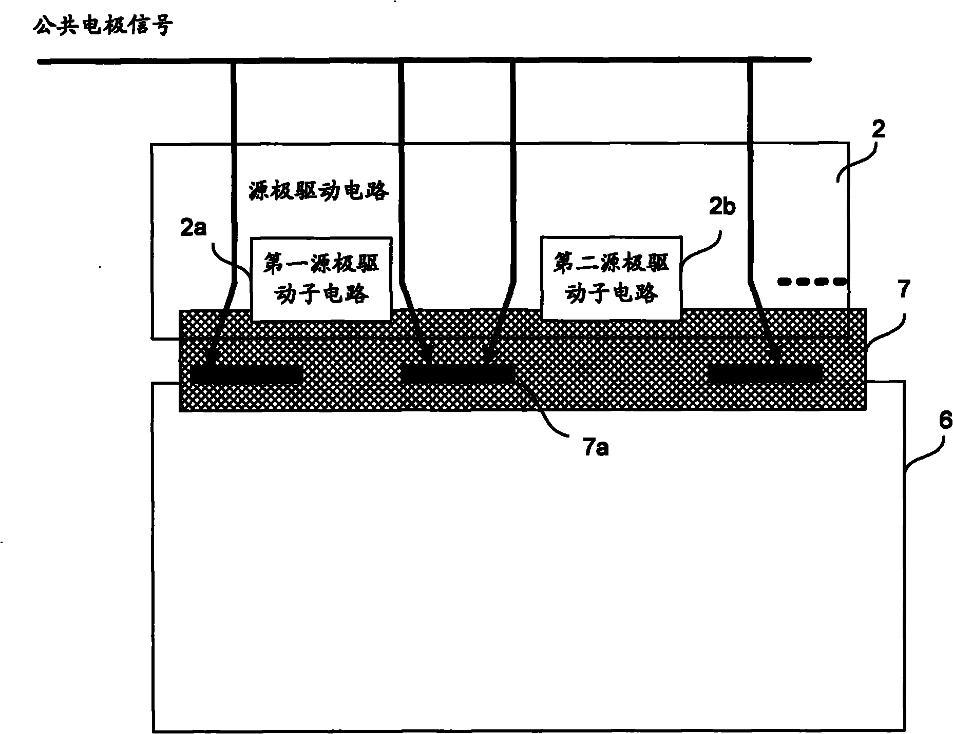
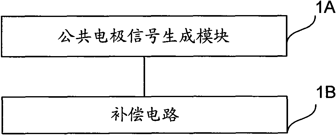
[0026] Such as image 3 Shown is a schematic structural diagram of the TFT-LCD driving circuit of the present invention, the driving circuit includes a common electrode signal generation module 1A and a compensation circuit 1B for generating common electrode signals, and the compensation circuit 1B is connected to the common electrode signal generation module 1A and the panel for use respectively. It is connected to the electrode receiving the common electrode signal, and is used to compensate the voltage on the electrode used to receive the common electrode signal on the panel, so that the voltage on the electrode used to receive the common electrode signal at different positions on the panel reaches its respective target voltage.

[0027] The TFT-LCD driving circuit provided by the present invention adopts a compensation circuit to compensate the voltage on the electrodes on the panel for receiving common electrode signals, so that the voltages on the electrodes at different...


PUM


Abstract

The invention discloses a TFT-LCD (Thin Film Transistor-Liquid Crystal Display) drive circuit comprising a public electrode signal generating module and a compensating circuit, wherein the public electrode signal generating module is used for generating public electrode signals; the compensating circuit is connected with the public electrode signal generating module and an electrode which is arranged on a panel and is used for receiving the public electrode signals, the compensating circuit is used for compensating the voltage of the electrode used for receiving the public electrode signals so that the voltage of the electrodes for receiving the public electrode signals in different positions on the panel achieves respective target voltage. The TFT-LCD drive circuit can reduce TFT-LCD picture scintillation and residual direct-current components.

Description

technical field [0001] The present invention relates to liquid crystal display drive technology, in particular to a thin film transistor liquid crystal display (Thin Film Transistor Liquid Crystal Display, TFT-LCD for short) drive circuit. Background technique [0002] TFT-LCD mainly includes a liquid crystal panel, a gate drive circuit, a source drive circuit, a timing controller and a backlight source. The liquid crystal panel is composed of an array substrate, a color filter substrate, and liquid crystals arranged in between. The data lines and gate lines are formed on the array substrate, and the thin film transistor (Thin Film Transistor, TFT for short) arranged at the intersection of the gate lines and the data lines is used for The data signal is transmitted to the pixel electrode of the array substrate. Such as figure 1 Shown is a schematic structural diagram of a TFT-LCD drive circuit in the prior art, a timing controller (Timing Controller, TCON for short) 1 is u...

Claims


Application Information

Patent Timeline
Patent Type & Authority Applications(China)
IPC IPC(8): G09G3/36
Inventor 郑喆奎
Owner BOE TECH GRP CO LTD
Why Eureka
Try Eureka