Electronic transformer

An electronic transformer and iron core technology, applied in transformers, fixed transformers, inductors, etc., can solve the problems of unapproved and market access, potential safety hazards, etc.

Inactive Publication Date: 2011-04-13
OSRAM GMBH
View PDF11 Cites 10 Cited by
  • Summary
  • Abstract
  • Description
  • Claims
  • Application Information

AI Technical Summary

Problems solved by technology

However, since the secondary coil is in direct contact with the iron core, there are inevitably safety hazards, so that in some regions—such as Germany and ot

Method used


Image

  • Electronic transformer
  • Electronic transformer
  • Electronic transformer

Examples


Embodiment Construction

[0027] Exemplary embodiments of the present invention will be described in detail below with reference to the accompanying drawings.

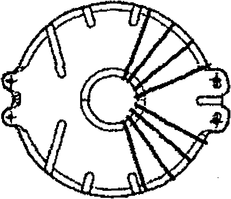
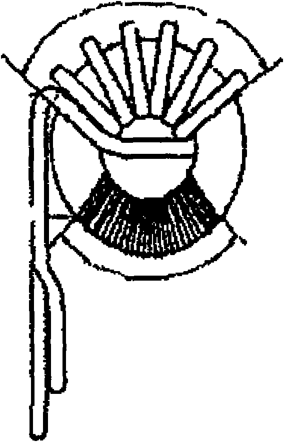
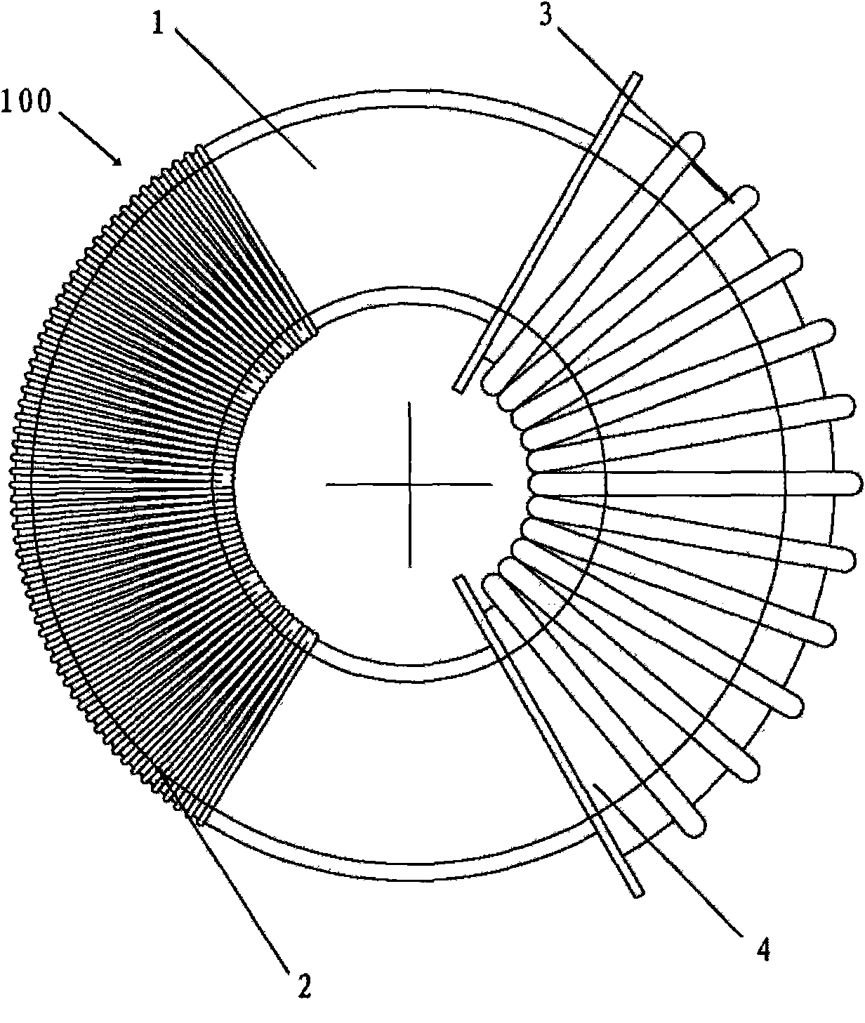
[0028] image 3 and Figure 4 are a plan view and a perspective view showing an electronic transformer according to an exemplary embodiment of the present invention, respectively. As shown, the electronic transformer is generally designated by the reference numeral 100 .

[0029] The electronic transformer 100 includes an iron core 1 , a primary coil (primary side) 2 and a secondary coil (secondary side) 3 . In this embodiment, the iron core 1 is an annular iron core, and preferably, the iron core 1 is a ferrite iron core, and has been properly coated with insulating varnish. The primary coil 2 and the secondary coil 3 are respectively wound on the iron core 1 , in other words, conductive wires are wound on the iron core to form coils. The conductive wire may comprise a single wire type or a braided (ie Litz wire) type, and is preferably en...


PUM


Abstract

The invention relates to an electronic transformer. The electronic transformer comprises an iron core, a primary coil, a secondary coil and an insulator, wherein the primary coil and the secondary coil are wound on the iron core, are oppositely arranged and are arranged along the iron core at a certain interval; the insulator is arranged on the secondary coil side of the iron core and is positioned between the iron core and the secondary coil to separate the iron core and the secondary coil. The electronic transformer improves the short circuit performance and has a simpler structure and a compacter shape on the premise of ensuring the insulativity of the electronic transformer.

Description

technical field [0001] The present invention relates to an electronic transformer, more specifically, to an electronic transformer that adopts a face-to-face design of a primary coil and a secondary coil, and only provides a skeleton on the side of the secondary coil. Background technique [0002] Electronic transformers are used in many applications, for example, in power supply units for halogen lamps. In this application, the input line voltage (for example, the mains voltage in China and most European countries is usually 220 to 240 volts, and in the Americas is usually 100 to 120 volts) is converted to 12 volts or 24 volts. output voltage in volts. [0003] At present, with the miniaturization of electrical equipment such as halogen lamps and the increasingly stringent requirements for electrical safety, there are also higher requirements for the size and insulation safety performance of electronic transformers. [0004] According to the requirements of IEC (Internati...

Claims


Application Information

Patent Timeline
IPC IPC(8): H01F30/16H01F27/32H01F27/24
CPCH01F30/16H01F38/10H01F27/324
Inventor 高建波郭远程曹永林海旋
Owner OSRAM GMBH
Why Eureka
Try Eureka