Rotating mechanism for spatial two-dimensional antenna

A technology of two-dimensional antenna and rotating mechanism, which is applied in the direction of antenna and electrical components, can solve the problems of low support rigidity and small rotation angle of two-dimensional antenna rotating mechanism, and achieve improved rigidity and strength, good interface and environmental adaptability, The effect of ensuring stability

Active Publication Date: 2011-04-13
XIAN INSTITUE OF SPACE RADIO TECH
View PDF3 Cites 14 Cited by
  • Summary
  • Abstract
  • Description
  • Claims
  • Application Information

AI Technical Summary

Problems solved by technology

[0005] At present, mechanical movable antennas are widely used in satellite-to-ground communications, but the two-dimensional antenna rotation mechanism used generally has a small rotation angle and relatively simple power feeding.

Method used


Image

  • Rotating mechanism for spatial two-dimensional antenna
  • Rotating mechanism for spatial two-dimensional antenna
  • Rotating mechanism for spatial two-dimensional antenna

Examples


Embodiment Construction

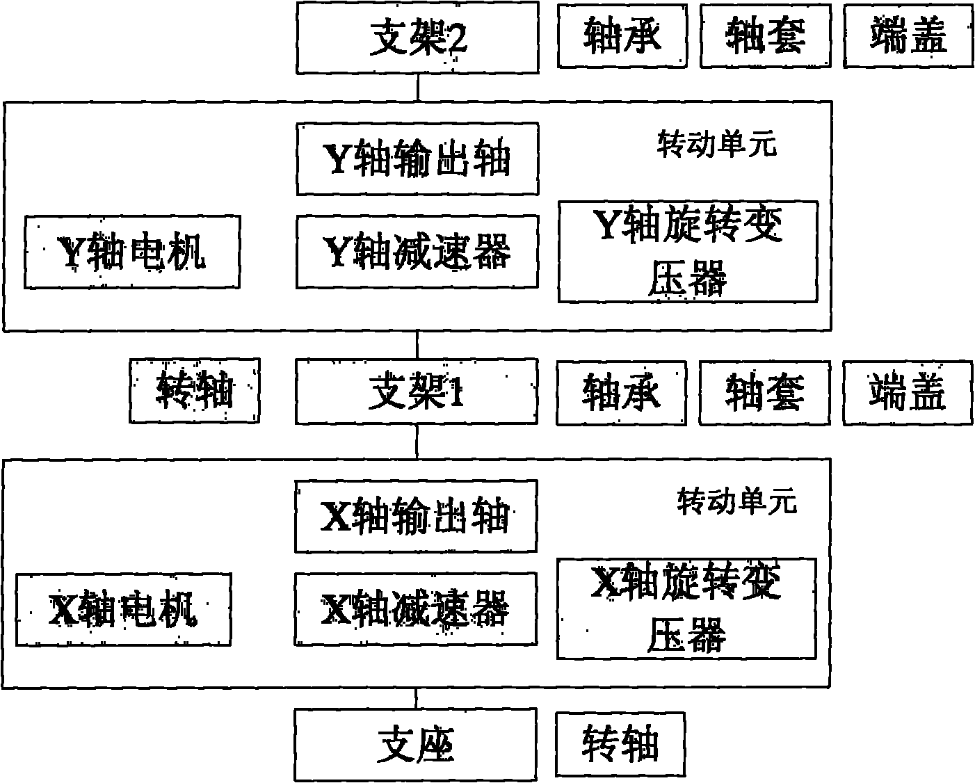
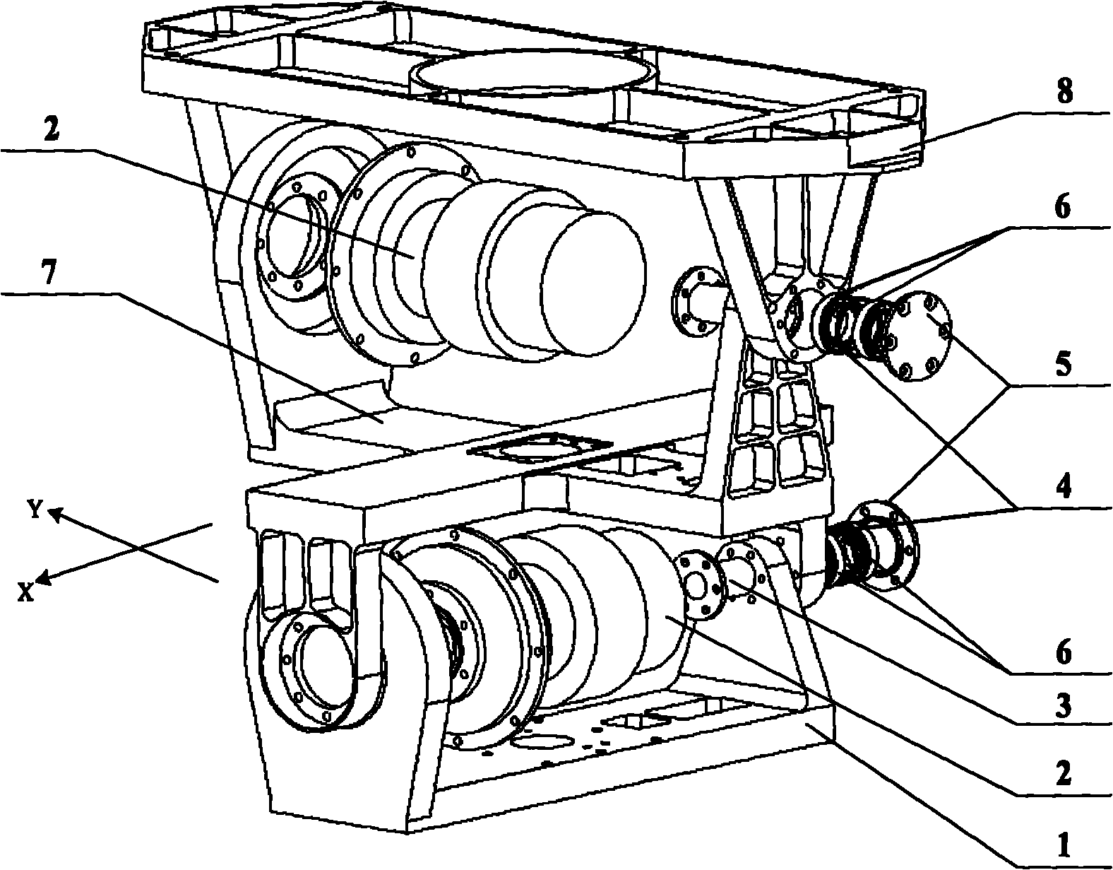
[0030] like figure 2 As shown, a spatial two-dimensional antenna rotation mechanism includes a support 1, a first bracket 7, a second bracket 8, two rotation units 2, a rotation shaft 3, a retaining ring 4, an end cover 5, and four bearings 6;

[0031] The first bracket 7 is a cross-orthogonal structure, respectively marked as the X-axis and the Y-axis. The directions of the arms at the two ends of the X-axis and the Y-axis are opposite. A transmission connection interface is provided on the arm at one end of the X-axis, and a rotating support is provided on the arm at the other end. Interface; one end of the Y-axis support arm is provided with a rotating unit connection interface, and the other end of the support arm is provided with a rotating support interface; the cross section of the support 1 is a U-shaped structure, one end of the U-shaped structure is a rotating unit connection interface, and the other end is a rotating support interface; The support 1 is placed insid...


PUM


Abstract

The invention relates to a rotating mechanism for a spatial two-dimensional antenna. A first frame is in a cross orthogonal structure marked respectively as an axis X and an axis Y. Directions of support arms at both ends of the axis X and the axis Y are opposite. The section of a support is in a U-shaped structure and the support is placed in the support arms at both ends of the axis X of the first frame to form a square cavity. A rotating unit connecting interface of the support is connected with a transmission connecting interface of the axis X. The section of the second frame is a U-shaped structure. Both ends of the support arms of the second frame are placed outside the support arms of the axis Y of the first frame to form a square cavity. A transmission connecting interface of the second frame is connected with a rotating unit connecting interface of the axis Y of the first frame. The output shafts of the two rotating units are respectively connected with the rotating unit connecting interfaces in the two square cavities as the driving parts of the axis X and the axis Y. Two rotating shafts respectively penetrate through the rotating support interfaces in the two square cavities. One ends of the rotating shafts are fixed on the internal walls of the square cavities via flanges. The retainer rings are placed in the middle of the two bearings and then mounted on the rotating shafts outside the square cavities in sequence and clamped by end covers.

Description

technical field [0001] The invention relates to a space application antenna rotation mechanism, in particular to a space application two-dimensional antenna rotation mechanism, which can be used for the two-dimensional rotation function of various mechanically movable space communication antennas and tracking antennas. It belongs to the field of space antenna technology. Background technique [0002] Mechanically movable antenna refers to the antenna technology that uses mechanical means to move the antenna beam. It is often used on high-gain spot beam antennas to achieve pointing or tracking of predetermined targets and establish communication links. With the construction of tracking and data relay satellites in my country, low-orbit user satellites are equipped with mechanically movable high-gain terminal antennas in order to establish inter-satellite links with relay satellites to achieve inter-satellite signal transmission. The antennas work in the Ka frequency band. The...

Claims


Application Information

Patent Timeline
IPC IPC(8): H01Q3/08
Inventor 张文会宋剑鸣冀有志张学刚张春史明张剑许智
Owner XIAN INSTITUE OF SPACE RADIO TECH
Why Eureka
Try Eureka