
Hybrid power device

A technology of hybrid power and driving force, applied in the direction of power plant, hybrid vehicle, air pressure power plant, etc., can solve the problems of power loss, traction torque increase, power loss increase, etc.

Inactive Publication Date: 2011-04-13
AISIN AI CO LTD +2
View PDF6 Cites 8 Cited by
  • Summary
  • Abstract
  • Description
  • Claims
  • Application Information

AI Technical Summary

Problems solved by technology

In this operating state, although the second friction clutch is in the disengaged state, since there is a traction torque caused by frictional resistance between the input member and the output member, power due to the traction torque is always generated during this operation. loss
When the second friction clutch is a wet clutch, the traction torque increases, so the power loss also increases

Method used


Image

  • Hybrid power device
  • Hybrid power device
  • Hybrid power device

Examples


Embodiment Construction

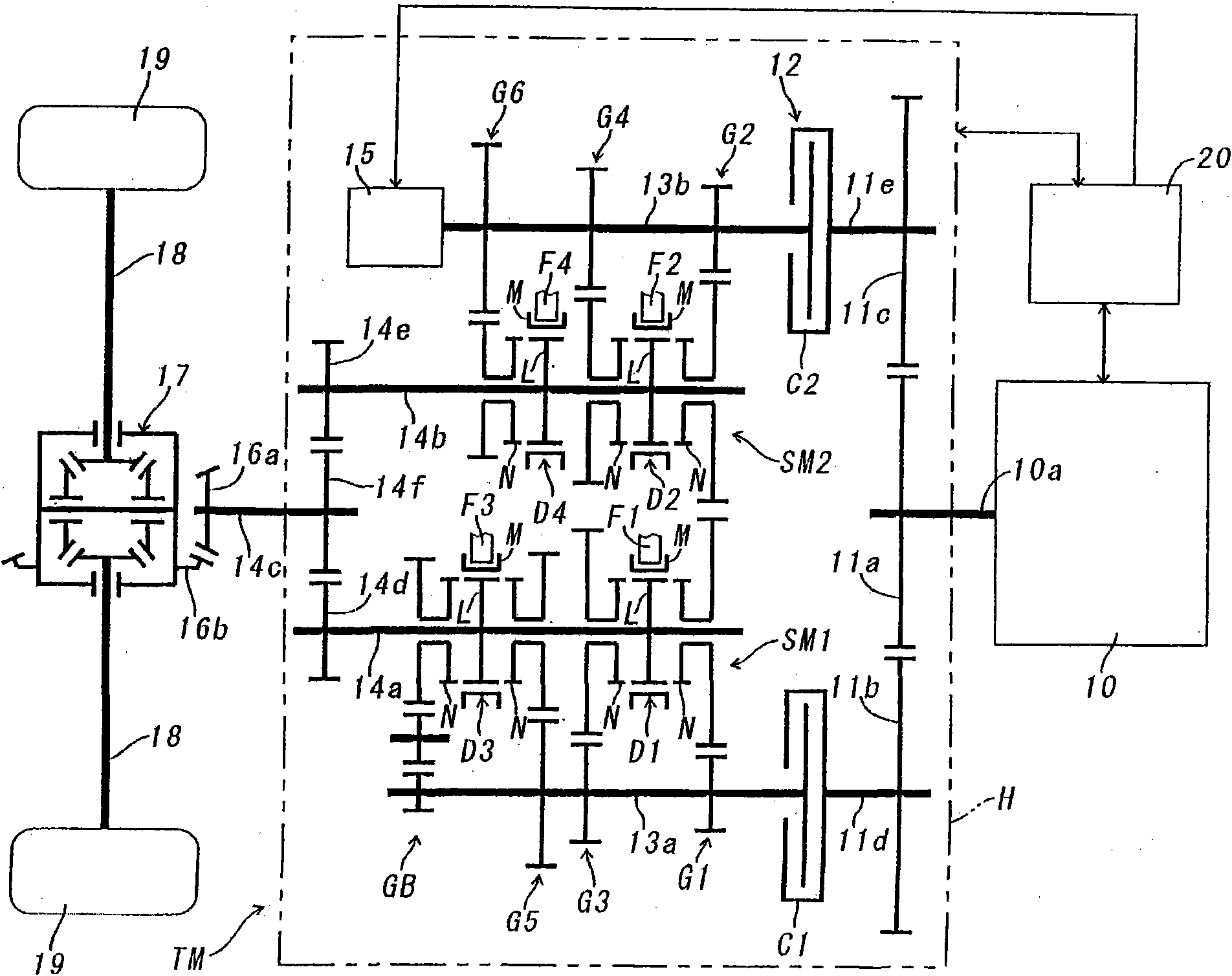
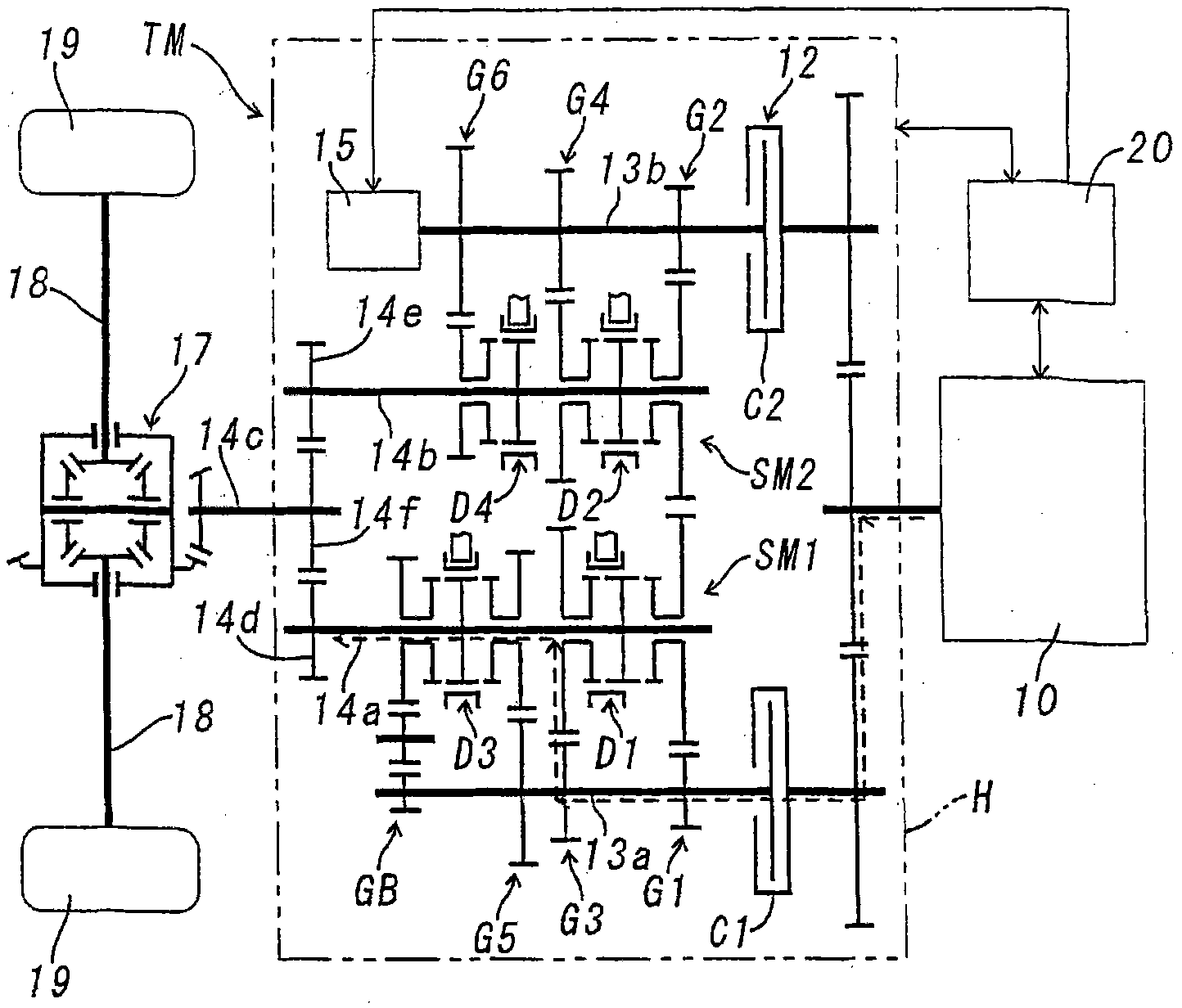
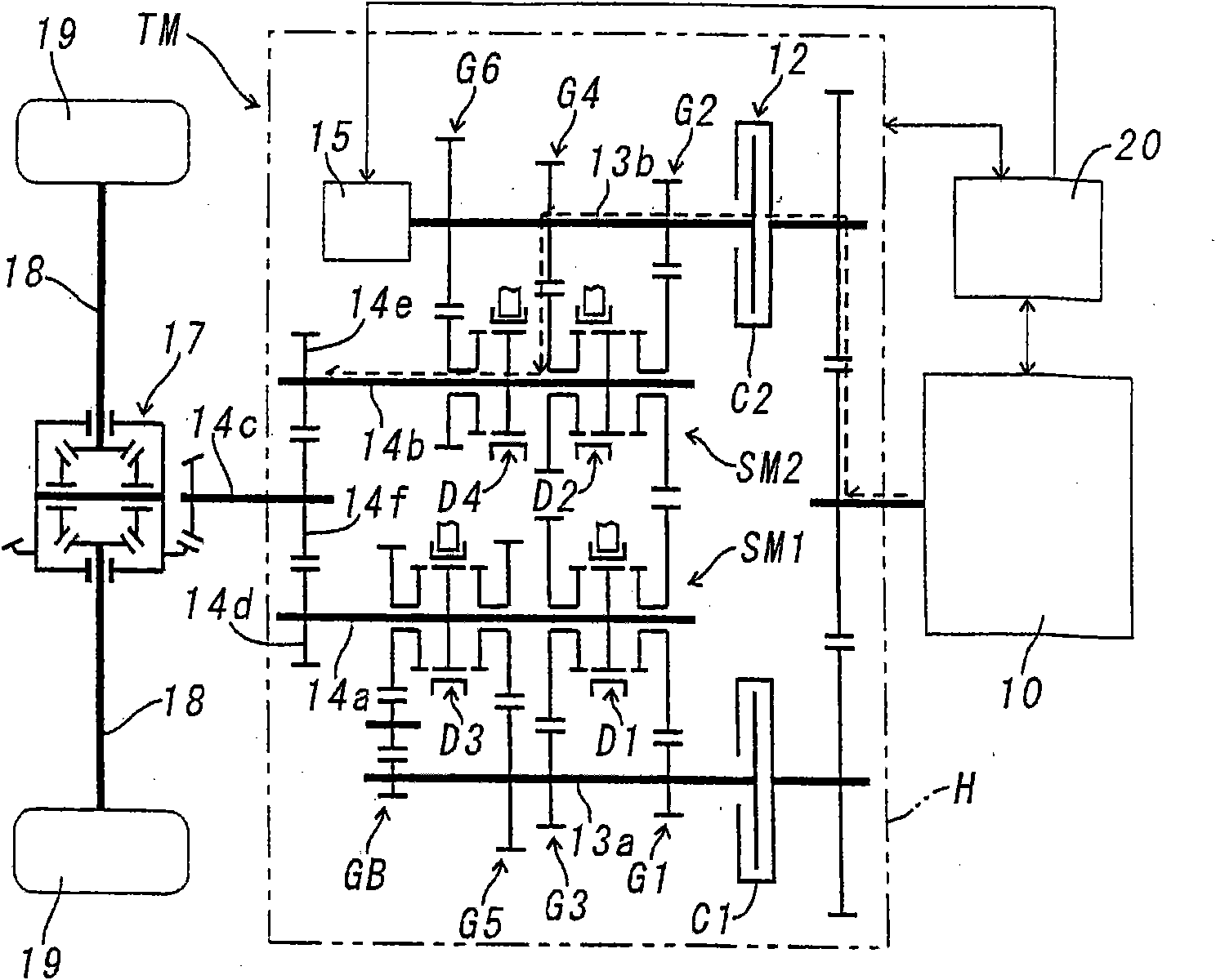
[0019] Below, refer to Figure 1-Figure 4 , the first embodiment of the hybrid power device of the present invention will be described. In this first embodiment, the control system of the hybrid power plant of the present invention is applied to figure 1 Shown is an automatic transmission TM with 6 forward speeds and 1 reverse speed.

[0020] This automatic transmission TM is a dual-clutch type. In the transmission case H, the first input shaft 13a and the second input shaft 13b, which are arranged parallel to each other and are supported so as to be freely rotatable, pass through the first friction clutch C1 and the second friction clutch C2, respectively. , is connected with the output shaft 10a of the engine 10 . The input member of the first friction clutch C1 is coupled to the support shaft 11d of the driven gear 11b, and the drive gear 11a that rotates integrally with the output shaft 10a of the engine 10 meshes with the driven gear 11b. Similarly, the input member o...


PUM


Abstract

A hybrid power device is provided with a first gear transmission mechanism mounted to a first input shaft to which drive power of an engine is transmitted through a first friction clutch, a second gear transmission mechanism mounted to a second input shaft to which the drive power of the engine is transmitted through a second friction clutch, a motor generator connected to the second input shaft, and a final output shaft connected to respective output shafts of both the gear transmission mechanisms. When the motor generator functions as the electric motor to drive an engine, the second friction clutch is released while the engine is activated, and when the first gear transmission mechanism selects any shift step, the first and the second friction clutches are together engaged by transmitting the drive of the engine and the motor generator to the output shaft through the shift step selected by the first gear transmission mechanism.

Description

technical field [0001] The present invention relates to a vehicle hybrid device, and more particularly to an improvement for reducing power loss generated in a power transmission system during a hybrid operation in a hybrid device suitable for a dual-clutch vehicle transmission. Background technique [0002] Japanese Patent Application Laid-Open No. 2005-186931 discloses a hybrid device employing such a dual clutch. The hybrid device has a first input shaft and a second input shaft which are coaxially arranged and can rotate relative to each other and selectively transmit the driving force of the engine through a dual clutch, and are respectively installed on the first output shaft arranged in parallel with the two input shafts. The 1st gear transmission mechanism and the 2nd gear transmission mechanism on the shaft and the 2nd output shaft, and the 1st gear transmission mechanism and the 2nd gear transmission mechanism connected with the 2nd input shaft, work as a motor aft...

Claims


Application Information

Patent Timeline
Patent Type & Authority Applications(China)
IPC IPC(8): B60W10/02B60K6/48B60K6/547B60L11/14B60W10/04B60W10/06B60W10/08B60W10/10B60W20/00F02D29/00F02D29/02F16H61/02F16H63/40F16H59/74F16H61/688B60L50/16F16H61/68F16H61/682F16H63/50
CPCB60K6/48F16H3/006B60W20/00B60W10/113B60K6/547B60K6/36F16H61/688B60W10/08B60W10/06B60W10/02Y02T10/6221B60Y2400/428Y02T10/6286Y02T10/62B60W20/40
Inventor 丹波俊夫福原裕一佐佐木环田畑满弘大村雅洋
Owner AISIN AI CO LTD
Learn More