Air pressure control valve and air pump control system using same

A technology of air pressure control and control system, applied in the direction of pump control, pump components, variable capacity pump components, etc., can solve the problems of increased power consumption, energy loss, complicated structure, etc., and achieve the effect of improving the utilization rate

Active Publication Date: 2013-06-26
LONGKOU ZHONGYU THERMAL MANAGEMENT SYST SCIAND TECH
View PDF6 Cites 8 Cited by
  • Summary
  • Abstract
  • Description
  • Claims
  • Application Information

AI Technical Summary

Problems solved by technology

[0002] The air pump is driven by the power of the engine. When the engine is working, the gas compression mechanism (piston, crankshaft, etc.) of the air pump is always working. Along with the power output, there are losses such as friction. When the speed is too high or the gas consumption is small, the compressed gas exceeds Safety pressure needs to be discharged, and energy is lost in vain
[0003] In order to solve the above problems, some methods use a check valve to open the outlet hole of the air pump to relieve pressure, so that the air pump has no power output, but there is still friction loss; some methods use an electromagnetic clutch installed between the engine and the crankshaft of the air pump, through the electromagnetic clutch. The crankshaft transmits torque. When the pressure in the air pump storage tank reaches the set value, the control system disengages the electromagnetic clutch and stops transmitting torque to the air pump crankshaft. When the pressure in the air pump storage tank is lower than the set value, the control system turns the electromagnetic clutch The clutch is closed to drive the crankshaft to rotate, which effectively reduces the friction loss of the air pump compression mechanism, but the electromagnetic clutch needs to be energized to the electromagnetic coil to work, the structure is complicated, and the power consumption needs to be increased

Method used


Image

  • Air pressure control valve and air pump control system using same
  • Air pressure control valve and air pump control system using same
  • Air pressure control valve and air pump control system using same

Examples


Embodiment Construction

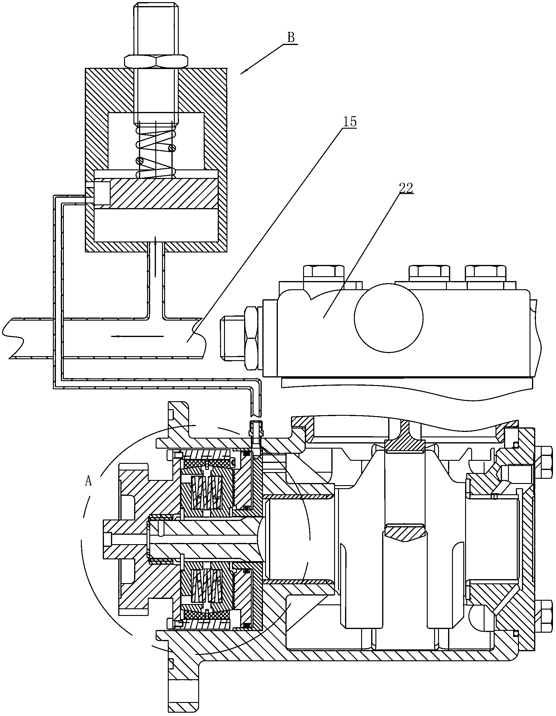
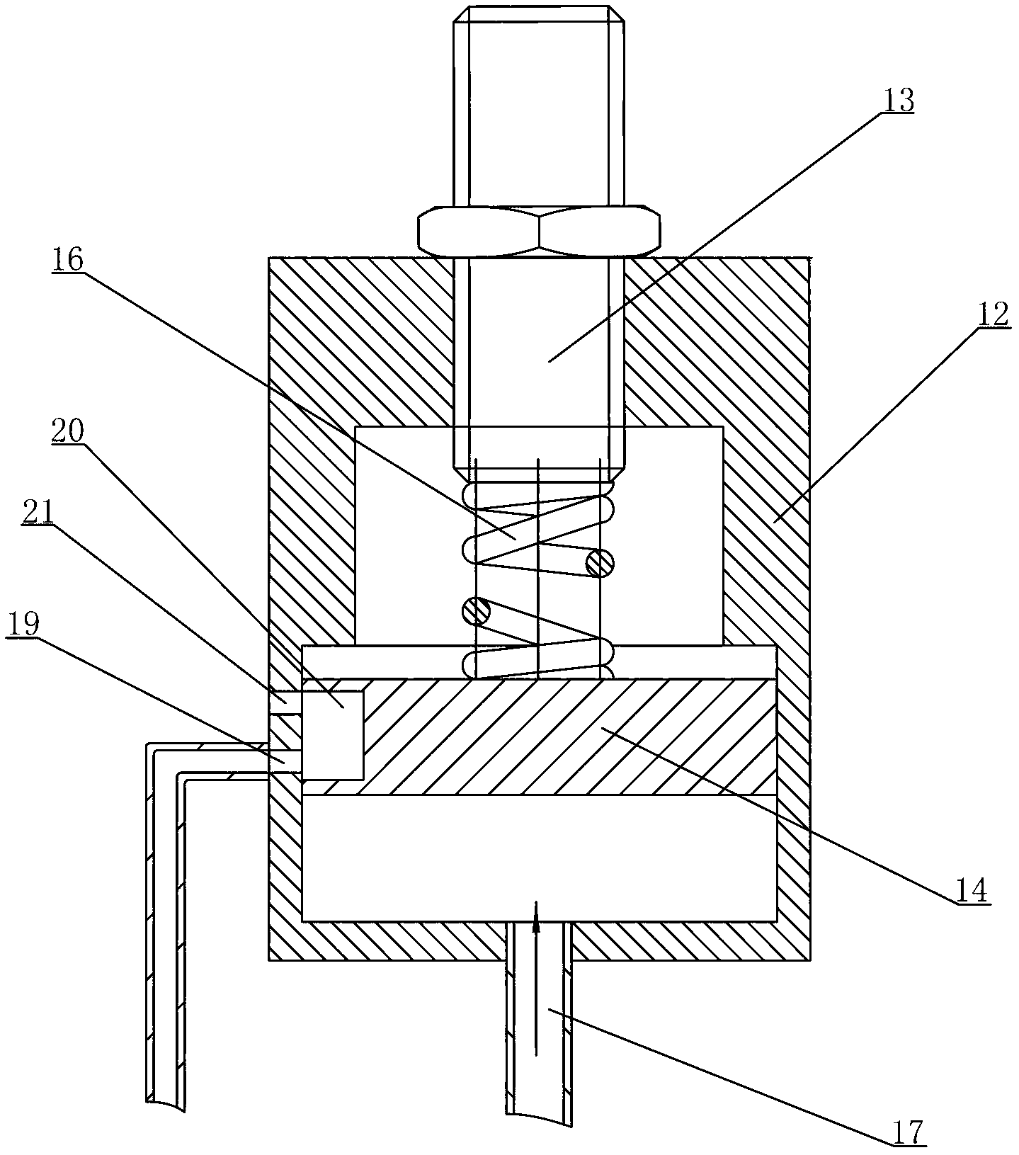
[0024] Such as figure 1 As shown, the air pump control system in this embodiment includes a friction coupling clutch (at A in the figure), an air pressure control valve (at B in the figure) and a shunt pipe 15 .

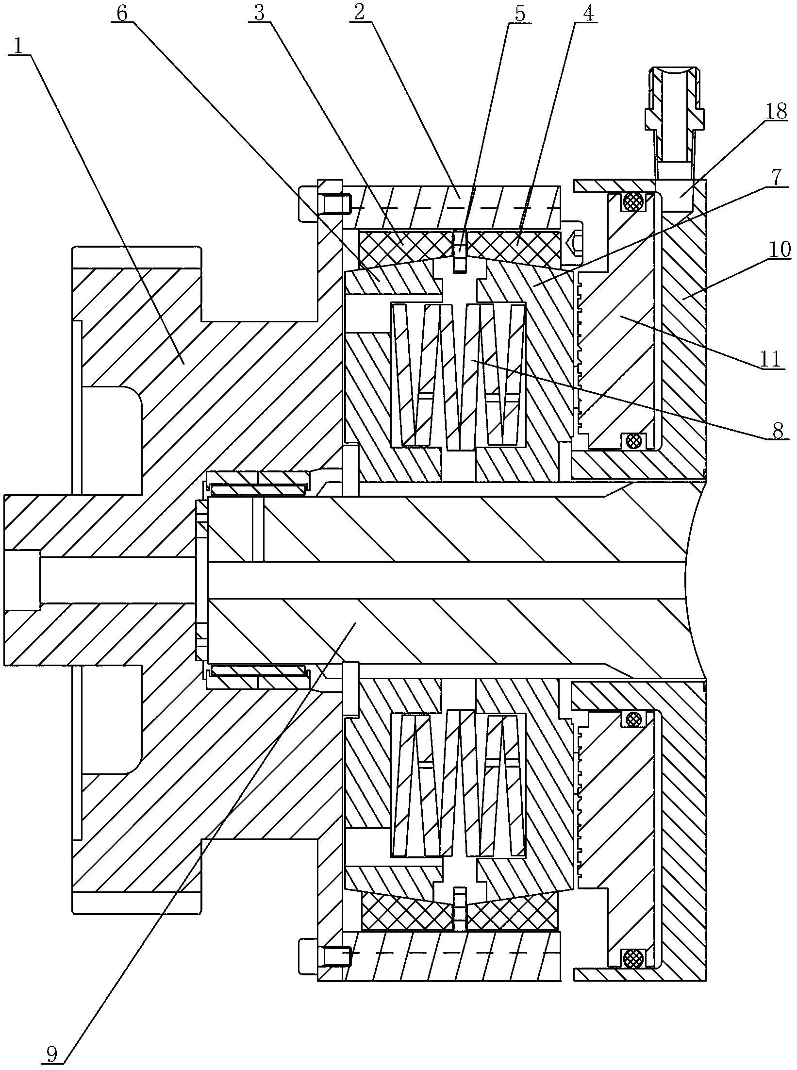
[0025] Such as Figure 2a As shown, the friction coupler includes a transmission wheel 1, a spline sleeve 2, a friction hub and a friction wheel. The transmission wheel is a gear that rotates driven by the output shaft of the engine. The spline sleeve 2 is connected with the gear 1 and rotates with the gear 1. . The friction hub is radially located inside the spline sleeve 2, and the outer surface of the friction hub has a keyway that matches the key of the spline sleeve 2, so that the friction hub can rotate together with the spline sleeve 2. The inner diameter of the friction hub extends from both ends to The middle gradually increases, and the inner surface is a left-right symmetrical conical surface structure. The friction hub is composed of a left-right symmet...


PUM


Abstract

The invention relates to an air pressure control valve and an air pump control system using the same. The air pressure control valve and the air pump control system using the air pressure control valve can effectively improve the utilization rate of energy, control the air pressure in the air pump to be stabilized in a certain value, and are free of electric energy loss. The air pressure control valve comprises a cylinder body, a pressure regulating rod, a first piston and a first elastic component, wherein the first piston is located in the cylinder body, the pressure regulating rod stretches in the cylinder body, one end of the first elastic component is connected on the pressure regulating rod, the other end of the first elastic component is connected on the first piston, an air inlet pipe is connected on the wall of the cylinder body, the wall is located on one side, away from the first elastic component, of the first piston, a first air hole is formed in the side wall of the cylinder body, and a second air hole is further formed above the first air hole and communicated with the atmosphere.

Description

technical field [0001] The invention relates to an air pressure control valve and a control system applied on an air pump to cooperate with a friction coupling clutch to control the operation of the air pump. Background technique [0002] The air pump is driven by the power of the engine. When the engine is working, the gas compression mechanism (piston, crankshaft, etc.) of the air pump is always working. Along with the power output, there are losses such as friction. When the speed is too high or the gas consumption is small, the compressed gas exceeds When the safety pressure needs to be discharged, the energy is lost in vain. [0003] In order to solve the above problems, some methods use a check valve to open the outlet hole of the air pump to relieve pressure, so that the air pump has no power output, but there is still friction loss; some methods use an electromagnetic clutch installed between the engine and the crankshaft of the air pump, through the electromagnetic ...

Claims


Application Information

Patent Timeline
Patent Type & Authority Applications(China)
IPC IPC(8): F04B39/10F04B49/22
Inventor 王兆宇邢子义李萍
Owner LONGKOU ZHONGYU THERMAL MANAGEMENT SYST SCIAND TECH
Why Eureka
Try Eureka