
High-speed wire coating device and method

A technology for equipment and equipment operation, which is applied in coatings, textiles and papermaking, and devices for coating liquids on surfaces, etc. It can solve problems such as restrictions, easy blockage of devices, and increased speed of cord travel.

Active Publication Date: 2011-04-13
MICHELIN & CO CIE GEN DES ESTAB MICHELIN
View PDF1 Cites 3 Cited by
  • Summary
  • Abstract
  • Description
  • Claims
  • Application Information

AI Technical Summary

Problems solved by technology

However, these devices can prove to be limited, as the devices themselves tend to become clogged due to the multiple contacts that exist between the cord and the drain, limiting their ability to perform their function, especially for the apparent productivity , especially when it is desired to increase the speed of travel of the cord

Method used


Image

  • High-speed wire coating device and method
  • High-speed wire coating device and method

Examples


Embodiment Construction

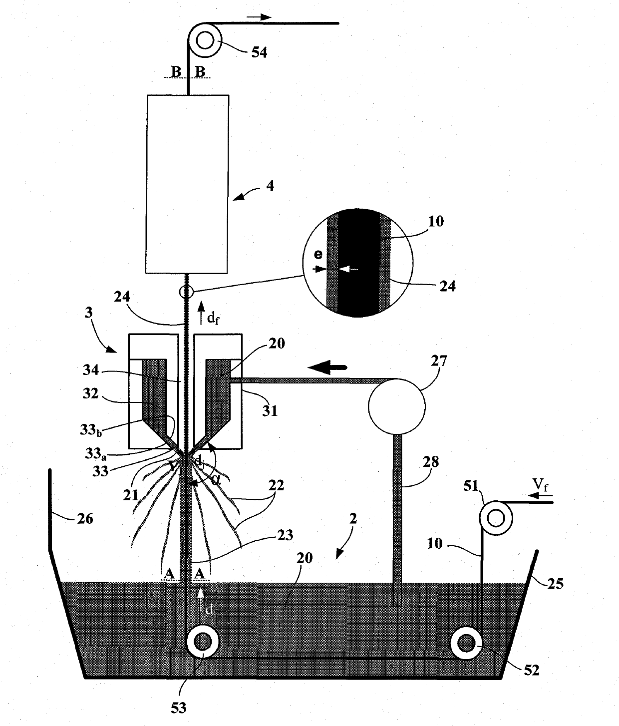
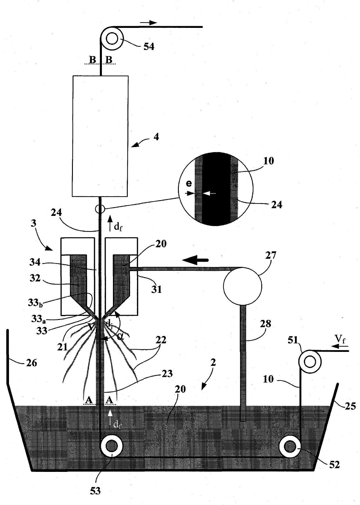
[0022] The device on which this description is based comprises impregnation means 2, drainage means 3, treatment means and means formed by turning pulleys, which enable the cord 10 to be impregnated from the inlet (51) to the outlet (54) of the device Travels between devices (52, 53) and through impregnation devices (52, 53).

[0023] The impregnation device 2 is formed, for example, by a tank 25 containing the treatment liquid 20 . The treatment liquid may be a solute dissolved in a solvent or an organic composition capable of curing under the action of a heat or energy source such as laser light or ultraviolet radiation.

[0024] A drive means (not shown), such as a motorized pulley, drives the continuous cord 10 through the tank 25 from a cord source (not shown). cord at speed V f Move down through processing equipment. On leaving the plant, the cords can be repackaged for subsequent manufacturing steps, or they can be integrated directly into the material to be reinforc...


PUM


Abstract

Device for continuously depositing a treatment substance (20) on the surface of a wire (10), comprising: impregnation means (2) for impregnating by dipping the wire into a bath intended to contain a solution of the treatment substance in liquid form (20), through which bath the wire runs when the device is in operation; draining means (3) placed downstream of the impregnation means (2), capable of removing the excess liquid (22) entrained by the wire; treatment means (4) placed downstream of the draining means (3), capable of making the liquid solution remaining on the wire solidified; and means (51, 52, 53, 54) for guiding and running the wire from the inlet to the outlet of the device along a direction df at a speed Vf, characterized in that the draining means (3) include means capable of spraying said treatment liquid at an appropriately regulated speed Vj towards the wire (10) in the form of jets (21) that converge in all directions dj making an obtuse angle a with the direction df in which said wire runs, so as to adjust the thickness e of liquid remaining on the wire on leaving said draining means (3).

Description

technical field [0001] The present invention relates to the field of manufacture of cores and cords, and more specifically to the steps of processing performed on these cords. Background technique [0002] In many processes it has proven useful to deposit a layer of controlled thickness of a given substance on the surface of the cord, so that the cord can be more easily handled in subsequent manufacturing steps. [0003] Such a case arises, for example, when it is necessary to use cords as fibers for reinforcing plastics. The cooperation between these two components is then made as effective as possible by depositing a bonding substance on the surface of the cord, while it is necessary to treat the cord so that it bonds perfectly to the matrix of the material being treated. This type of application is widely used in the tire industry or in the reinforced plastics industry. [0004] In the context of this specification, the term "cord" should be understood in a very broad s...

Claims


Application Information

Patent Timeline
Patent Type & Authority Applications(China)
IPC IPC(8): D06B3/06D06B15/00B05D3/00B05D7/20
CPCD07B7/145D07B2201/2012D07B2501/2046D07B2207/404B05D2256/00B05D1/18D06B23/24D06B15/00D06B3/06B05C3/125B05D3/067D07B1/0666B05C3/12B05D7/20B05C3/132B05D3/0254D07B2801/60
Inventor H·安坎G·谢弗雷尔
Owner MICHELIN & CO CIE GEN DES ESTAB MICHELIN
Learn More