Efficient physical layer preamble format
A preamble and format technology, applied in the field of effective physical layer preamble format, can solve the problems of poor frame timing accuracy, low sensitivity, and limiting overall performance
- Summary
- Abstract
- Description
- Claims
- Application Information
AI Technical Summary
Problems solved by technology
Method used
Image

Examples
Embodiment Construction
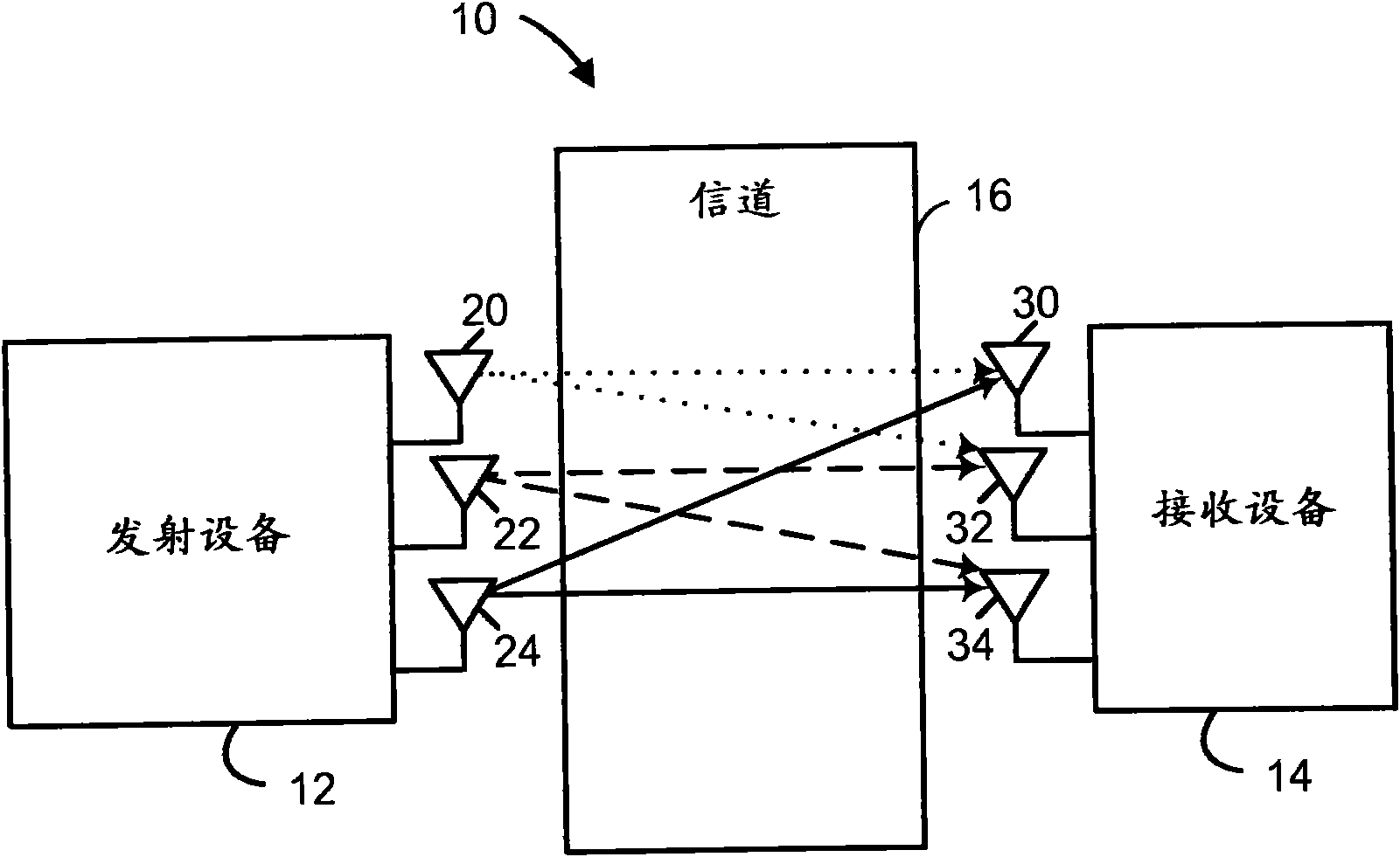
[0068] figure 1 is a block diagram of an example wireless communication system 10 in which devices such as transmitting device 12 and receiving device 14 can transmit and receive data packets over a shared wireless communication channel 16 . In one embodiment, devices 12 and 14 may communicate according to a communication protocol using an efficient PHY preamble format detailed below. Each of devices 12 and 14 may be, for example, a mobile station or a non-mobile station equipped with a set of one or more antennas 20-24 and 30-34, respectively. although figure 1 The wireless communication system 10 shown in FIG. 1 includes two devices 12, 14 each having three antennas, but the wireless communication system 10 may of course include any number of devices each equipped with the same or a different number of antennas (e.g. , 1, 2, 3, 4 antennas, etc.).
[0069] Also, it will be noted that although figure 1 The wireless communication system 10 shown in includes a transmittin...
PUM
 Abstract
Description
Claims
Application Information