Heating lamp tube mounting structure of oven

A technology of installation structure and lamp tube, which is applied in glass forming, glass blowing, application, etc., can solve the problems of damage to the heating lamp tube and short service life, so as to reduce the probability of heating the lamp tube, reduce the production cost, and achieve good performance. The effect of applicability

Inactive Publication Date: 2011-04-20
林子祥
View PDF3 Cites 3 Cited by
  • Summary
  • Abstract
  • Description
  • Claims
  • Application Information

AI Technical Summary

Problems solved by technology

[0004] In order to overcome the disadvantages that the heating lamp tube of the existing oven is easily damaged due to vibration and has a short service life, the present invention provides a heating lamp for an oven that can effectively reduce the damage to the lamp tube due to vibration and prolong the service life of the lamp tube. Tube mounting structure

Method used


Image

  • Heating lamp tube mounting structure of oven
  • Heating lamp tube mounting structure of oven
  • Heating lamp tube mounting structure of oven

Examples


Embodiment Construction

[0017] The present invention will be further described below in conjunction with the accompanying drawings.

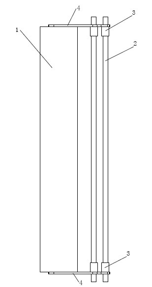
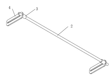
[0018] refer to Figure 1~Figure 3 , a heating lamp installation structure for an oven, including a lamp bracket 1 for installing a heating lamp, a sheath 3 is installed at both ends of the heating lamp 2, and the sheath 3 is a stepped shaft structure. The big end of the stepped shaft structure is provided with a blind hole, the end of the heating lamp is plugged into the blind hole, the small end of the stepped shaft structure is sleeved on the lamp tube support 4, and the lamp tube supports The base 4 is installed on the lamp tube support 1, and the stepped shaft structure is provided with a central through hole for the power cord to pass through.

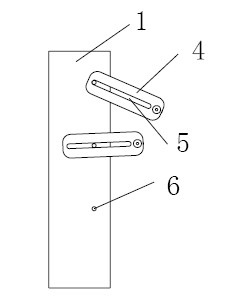
[0019] The end of the lamp support 4 is provided with a mounting hole, and the small end of the stepped shaft structure is inserted into the mounting hole.

[0020] An adjustment hole 5 is opened on the lamp tube suppor...


PUM


Abstract

The invention discloses a heating lamp tube mounting structure of an oven. The structure comprises a lamp tube bracket used for mounting a heating lamp tube, wherein a sheath is arranged at two ends of the heating lamp tube respectively; the sheath has a stepped shaft structure; a blind hole is formed at the big end of the stepped shaft structure; the end part of the heating lamp tube is inserted into the blind hole; the small end of the stepped shaft structure is sleeved on a lamp tube support; the lamp tube support is arranged on the lamp tube bracket; and a central through hole for a power wire to pass through is formed on the stepped shaft structure. The invention provides the heating lamp tube mounting structure of the oven, which can effectively reduce damage to the lamp tube due to vibration and prolong the service life of the lamp tube.

Description

technical field [0001] The invention relates to the field of bottle blowing machines, in particular to an oven for bottle blowing machines. Background technique [0002] The semi-automatic bottle blowing machine usually includes an oven and a mold clamping blow molding mechanism. The oven heats the tube blank to a set temperature. In the oven, the existing heating lamp tube is usually arranged on the lamp tube holder, and usually adopts a fixed installation method. For example, when the oven starts to vibrate, it is easy to cause the lamp tube to break, and the service life of the lamp tube is short. [0003] After the position of the heating lamp is determined, the distance between it and the preform station to be heated cannot be adjusted; the existing problem is: the arrangement of the heating lamp in a certain oven can only be applied to a specific corresponding type of preform Heating, because the heating lamp tube is fixedly installed, and the distance cannot be adjus...

Claims


Application Information

Patent Timeline
IPC IPC(8): B29C49/64C03B9/38B29L22/00
Inventor 林子祥
Owner 林子祥
Why Eureka
Try Eureka