Bridge erection method

A technology for bridges and beams, which is applied in the field of bridge erection after simple support first and then continuous, can solve the problems of construction and dismantling cost, labor and material, high requirements for support stability, affecting the clearance under the bridge, etc., and achieves convenient construction and driving comfort. good, holistic effect

Inactive Publication Date: 2011-04-20
SHANGHAI URBAN CONSTR DESIGN RES INST GRP CO LTD
View PDF3 Cites 24 Cited by
  • Summary
  • Abstract
  • Description
  • Claims
  • Application Information

AI Technical Summary

Problems solved by technology

The defect of this construction method: the bridge pier cover girder is exposed, which not only affects the clearance under the bridge, but also affects the beauty of the bridge
Defects of this construction method: high requirements for the stabili...

Method used


Image

  • Bridge erection method
  • Bridge erection method
  • Bridge erection method

Examples


Embodiment Construction

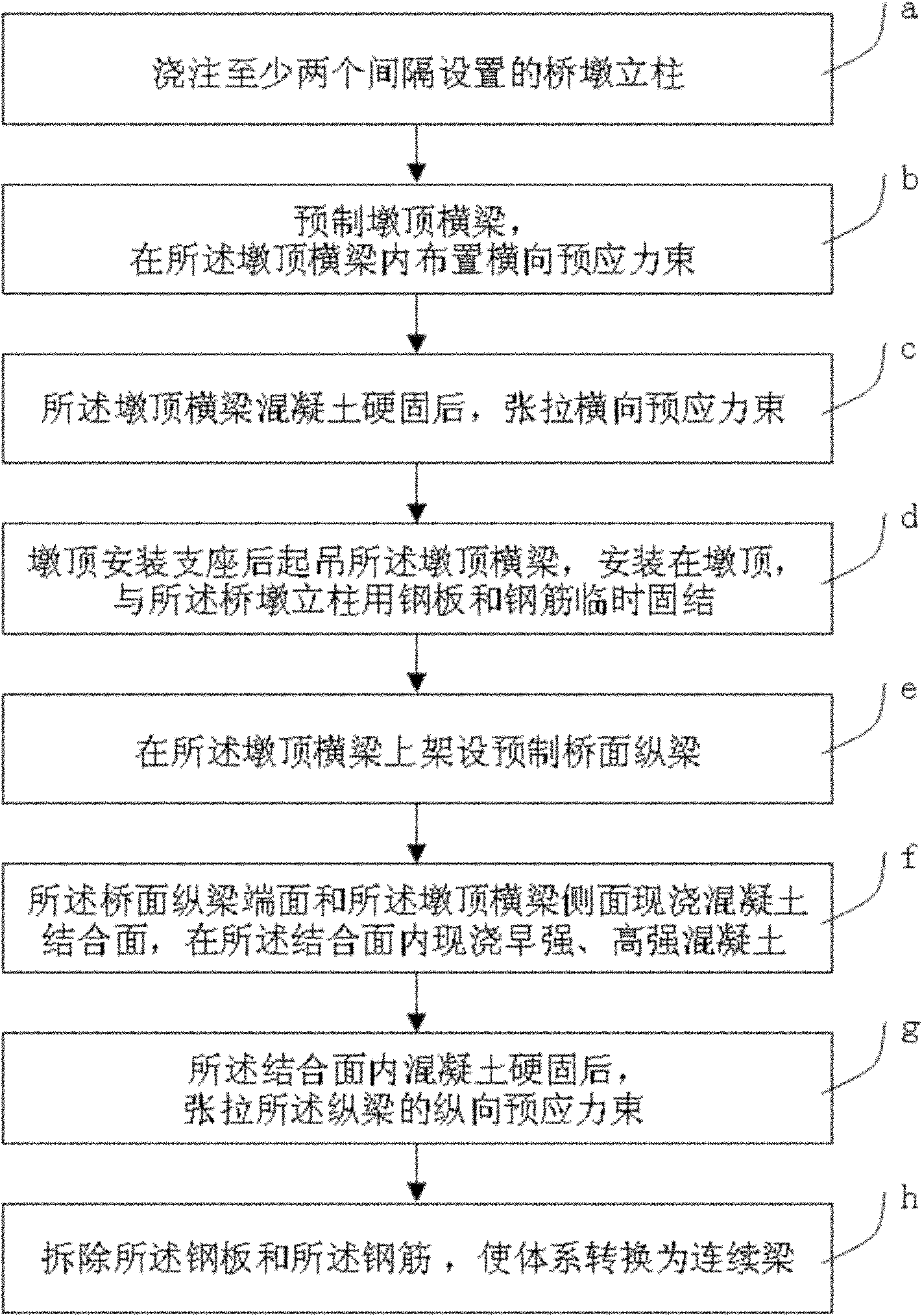
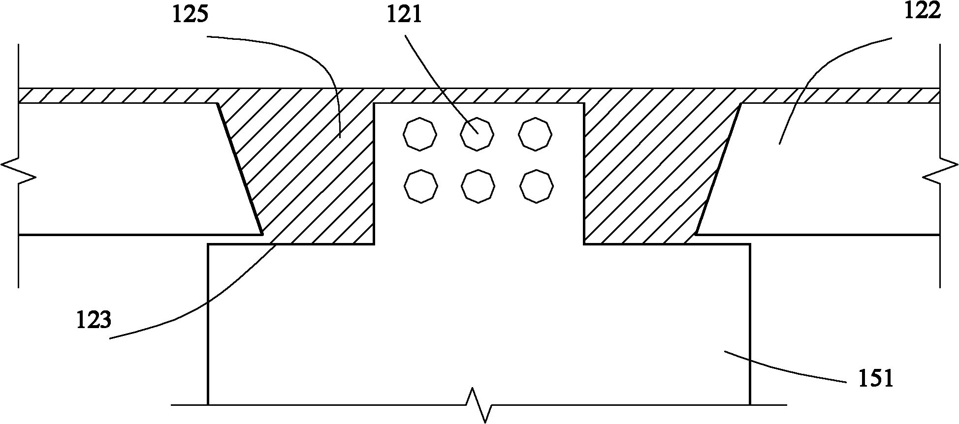
[0030] Such as figure 1 , is a flow chart of a bridge erection method provided by the present invention. Such as figure 2 , image 3 , Figure 4 and Figure 5 Shown, this bridge erecting method comprises the following steps:

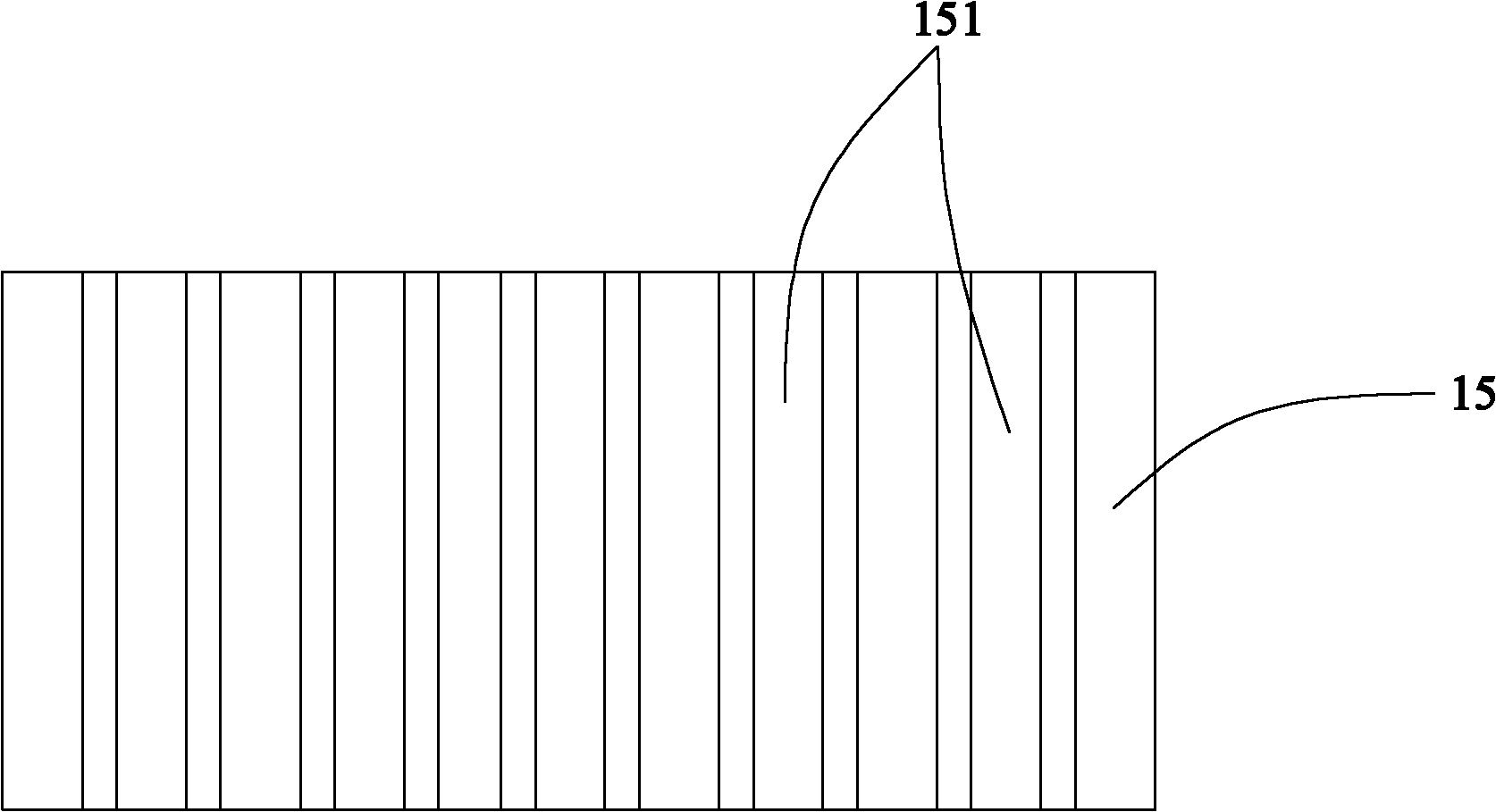
[0031] The cross-section of the prefabricated pier top beam 15 is inverted T-shaped 151, the beam height is slightly lower than the longitudinal prestressed beam, the inverted T-shaped cantilever 123 on the bottom surface can support the bridge deck longitudinal beam 122, the end surface of the bridge deck longitudinal beam 122 and the side surface of the inverted T pier top beam 151 are The cast-in-place concrete joint surface 125, the shear key on the joint surface 125 is composed of a plurality of rectangular or elongated key blocks (grooves), and the transverse prestressed beam 121 is arranged in the top beam of the inverted T pier according to the design requirements.

[0032] After the concrete of the prefabricated pier top beam 15 reaches th...


PUM


Abstract

The invention discloses a bridge erection method, which is a prefabricated pier-top beam method. The bridge erection method comprises the following steps of: casting at least two pier columns at intervals; prefabricating pier-top beams, and arranging transverse prestressing tendons in the prefabricated pier-top beams; after the setting of concrete, tensioning the transverse prestressing tendons; arranging supports at the tops of piers, hoisting the pier-top beams, arranging the pier-top beams at the tops of the piers, and temporarily fixedly connecting the pier-top beams and the pier columns by using steel plates and reinforcing steel bars; erecting prefabricated longitudinal deck beams on the pier-top beams; casting in-situ concrete joint surfaces on the end faces of the longitudinal deck beams and the lateral surfaces of the pier-top beams, and casting in-situ early-strength and high-strength concrete in the joint surfaces; after the setting of the concrete in the joint surfaces, tensioning longitudinal prestressing tendons of the longitudinal beams; and removing the steel plates and the reinforcing steel bars. The method greatly reduces the height of a structural building and reduces the deck elevation; and a freely supported structure is changed into a continuous structure by the cast-in-situ concrete so as to improve the integrity of a bridge, prolong the service life of the bridge, solve the problem of stress in construction stages and reduce the cost of engineering construction.

Description

technical field [0001] The invention relates to a bridge erecting method, in particular to a simply supported and then continuous bridge erecting method. Background technique [0002] At present, when erecting overpass bridges in cities, two methods are generally adopted, one is simply supported first and then continuous structure, and the other is simply supported structure-bridge deck continuous structure. Compared with the simply supported structure-bridge deck continuous structure, it has no continuous bridge deck structure that is easy to be damaged, so it has many advantages such as good durability, good driving comfort, and little impact on surrounding noise. [0003] There are two ways to simply support first and then continue: [0004] 1. The simply supported beam is erected on the cover beam first and then continued. The defect of this construction method is that the pier cover girder is exposed, which not only affects the clearance under the bridge, but also aff...

Claims


Application Information

Patent Timeline
IPC IPC(8): E01D21/00E04G21/12E01D19/00
Inventor 周良左涌吴刚黄锦源丁佳元闫兴非
Owner SHANGHAI URBAN CONSTR DESIGN RES INST GRP CO LTD
Why Eureka
Try Eureka