Supercharge Your Innovation With Domain-Expert AI Agents!

Multi-cylinder diesel engine

A diesel engine, multi-cylinder technology, applied in the direction of engine components, combustion engines, engine cooling, etc., to achieve the effects of suppressing common rail thermal damage, suppressing common rail thermal damage, increasing fuel temperature, and improving heat dissipation

Active Publication Date: 2014-12-10
KUBOTA CORP
View PDF6 Cites 0 Cited by
  • Summary
  • Abstract
  • Description
  • Claims
  • Application Information

AI Technical Summary

Problems solved by technology

[0007]Because the suction inlet of the suction manifold is arranged in front of the common rail, the engine cooling air from the engine cooling fan is blocked at the suction inlet and cannot Blowing onto the common rail reduces the heat dissipation of the common rail and easily causes thermal damage to the common rail and a rise in fuel temperature

Method used


Image

  • Multi-cylinder diesel engine
  • Multi-cylinder diesel engine
  • Multi-cylinder diesel engine

Examples


no. 1 approach

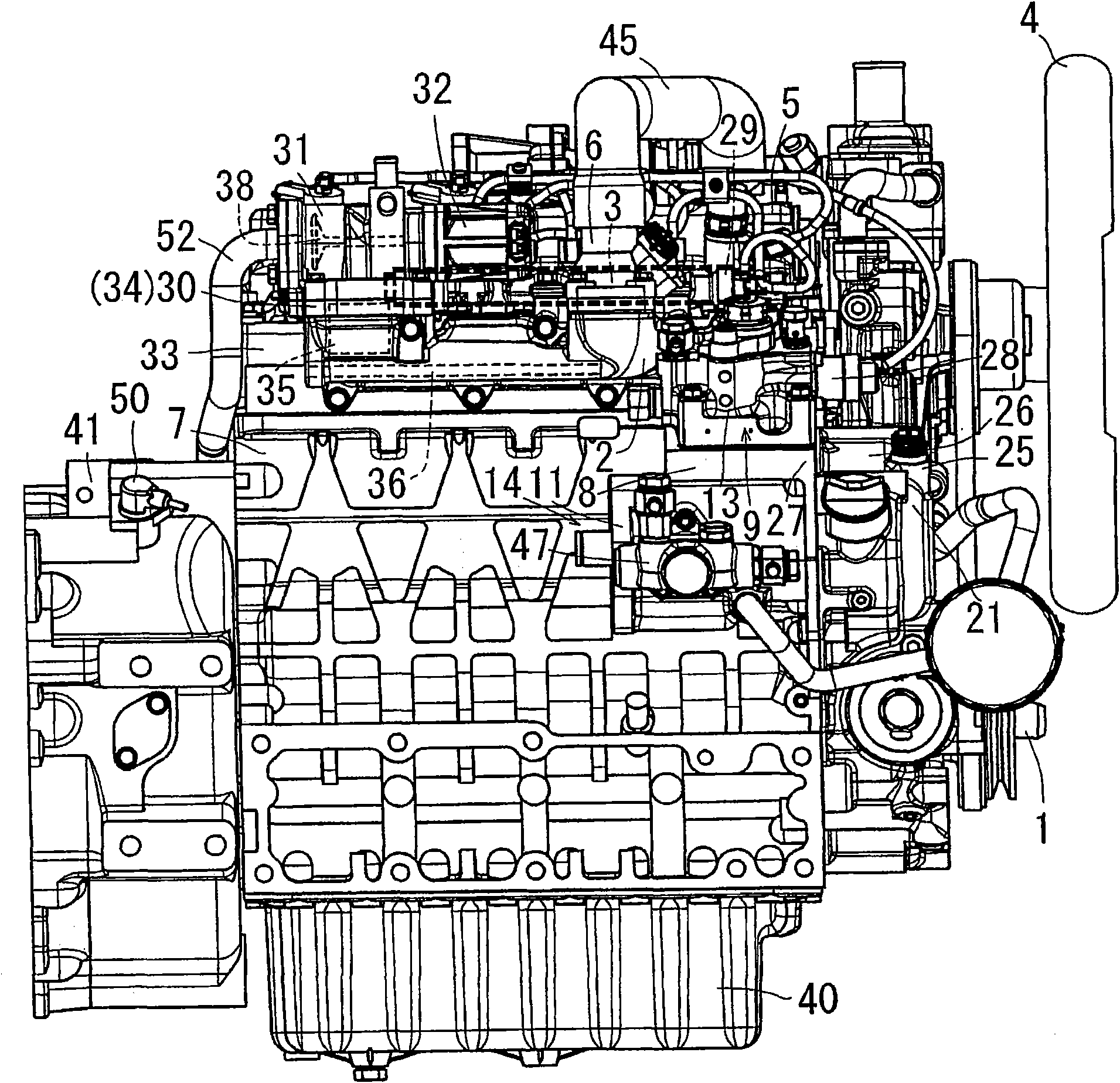
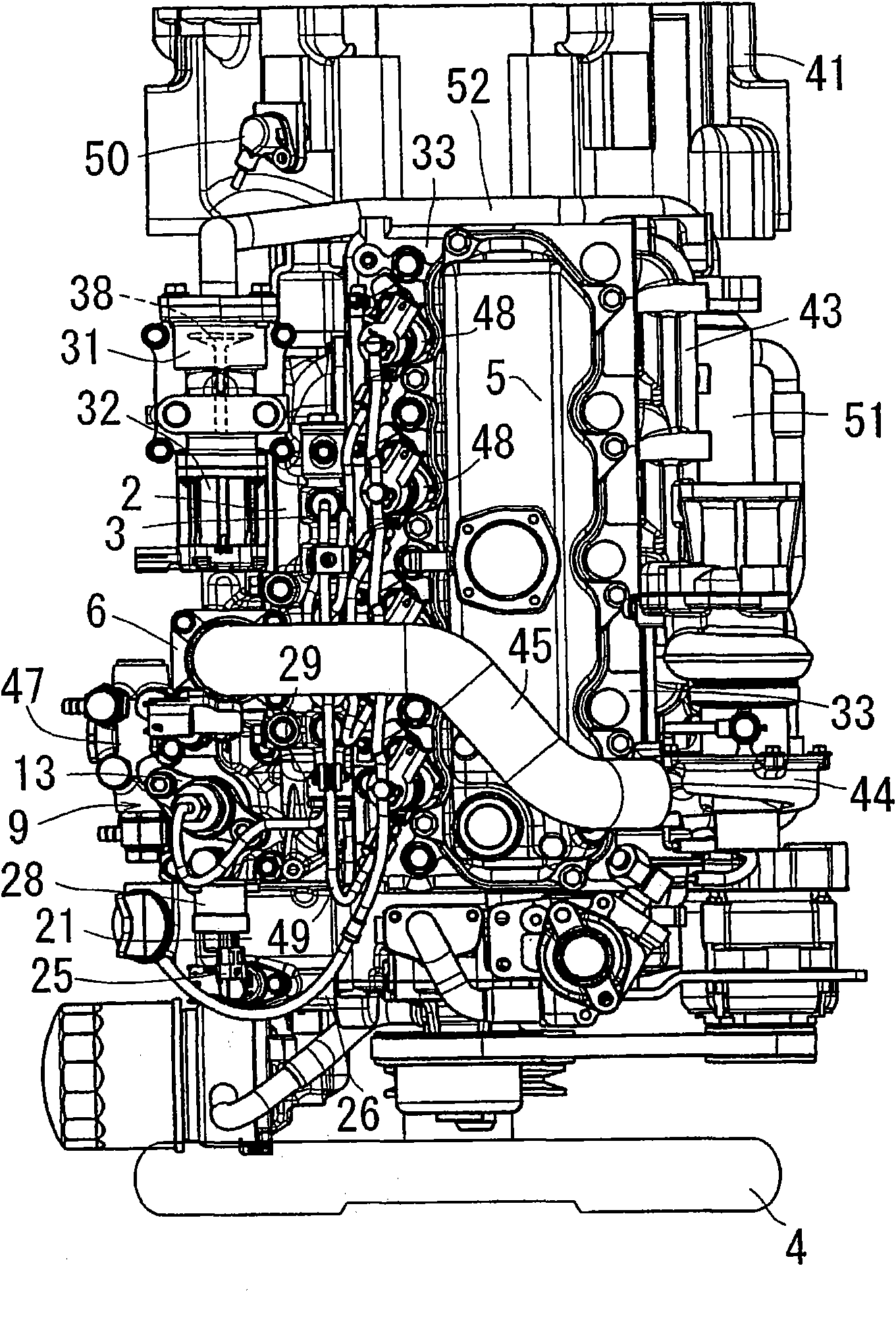
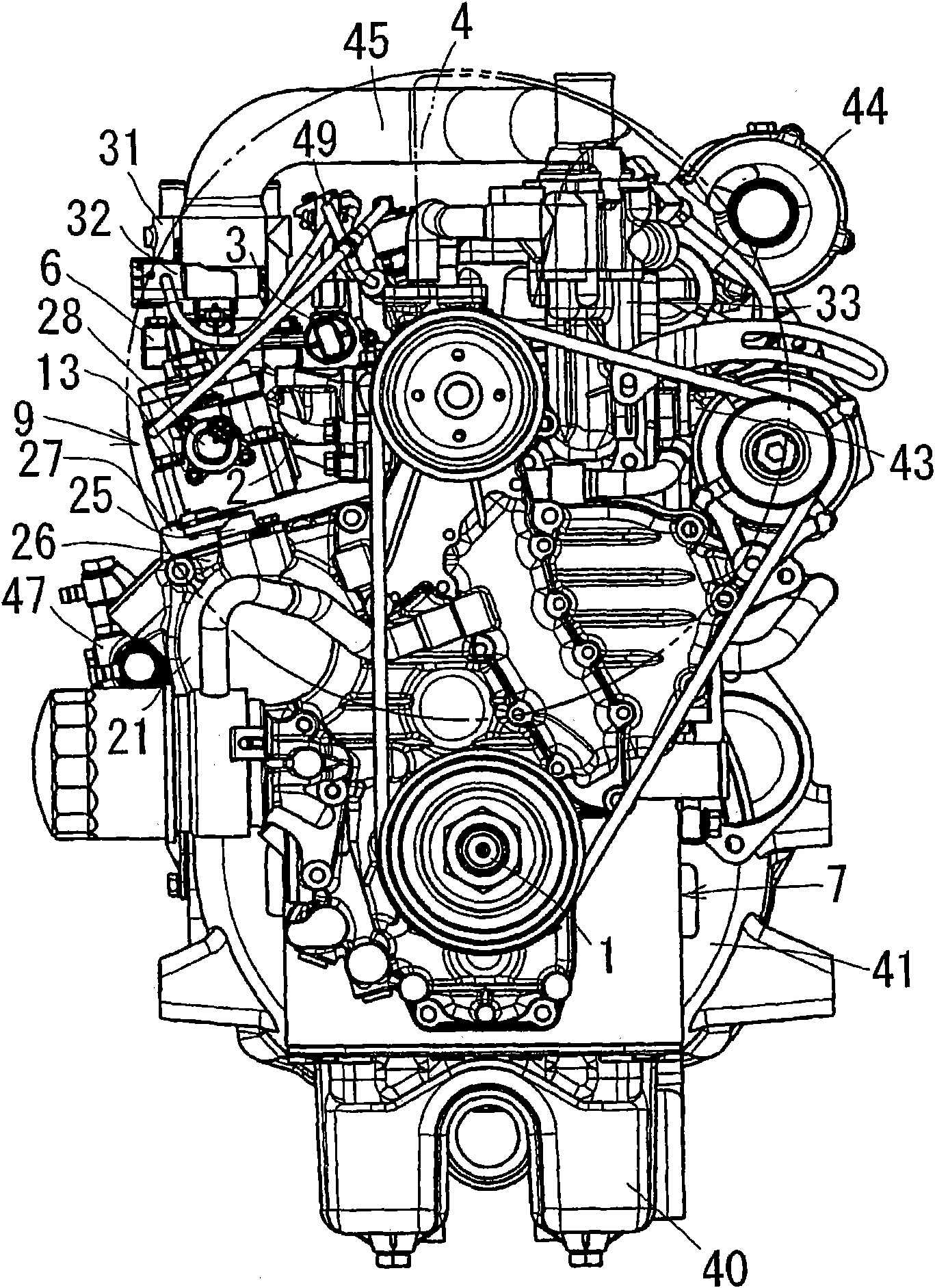
[0075] Such as image 3 As shown, with regard to the engine, a cylinder head 33 is assembled on the top of the cylinder block 7, a cylinder head cover 5 is assembled on the top of the cylinder head 33, an oil pan 40 is assembled on the bottom of the cylinder block 7, and an oil pan 40 is assembled on the bottom of the cylinder block 7. The gear box 21 is assembled in the part. Such as Figure 4 As shown, there is a flywheel housing 41 at the rear of the cylinder block 7 , and a flywheel 42 assembled on the crankshaft 1 is accommodated in the flywheel housing 41 .

[0076] Such as image 3 As shown, when viewed from the front of the engine, the intake manifold 2 is assembled on the left side of the cylinder head 33 , and the exhaust manifold 43 is assembled on the right side of the cylinder head 33 . A supercharger 44 is attached to an upper portion of the exhaust manifold 43 , and the intake air inlet portion 6 of the intake manifold 2 is supercharged from the supercharger ...


PUM


Abstract

A multi-cylinder diesel engine which has a common rail (3) extending in a fore-and-aft direction and is disposed above an intake manifold (2), and an engine cooling fan 4 is disposed at the front of the engine. A air intake portion (6) of the intake manifold (2) is disposed laterally outwardly of the common rail 3 and opposite a head cover (5). The common rail 3 is disposed in the path of cooling air blown by the engine cooling fan (4).

Description

technical field [0001] The present invention relates to a multi-cylinder diesel engine, and relates in detail to a multi-cylinder diesel engine capable of suppressing thermal damage of a common rail and an increase in fuel temperature. Background technique [0002] Conventionally, a multi-cylinder diesel engine has a structure in which a common rail facing the front-rear direction is arranged above the intake manifold, and an engine cooling fan is arranged on the front side of the engine with the crankshaft mounting direction as the front-rear direction (see Patent Literature 1). [0003] According to such an engine, there is an advantage that the heat of the cylinder head and the cylinder block hardly enters the common rail, and the common rail can be air-cooled by the engine cooling air from the engine cooling fan. [0004] However, in this prior art, there is a problem because the intake inlet of the intake manifold is arranged in front of the common rail. [0005] Pat...

Claims


Application Information

Patent Timeline
Patent Type & Authority Patents(China)
IPC IPC(8): F02M55/02F01P5/02F02M39/00
CPCF02M35/10216F02M35/10222F02M35/10144F02M35/10268F02M35/112F02M35/10111F02M39/005F01P1/06F02B3/06F02F7/0068F02F7/007F02M63/02F02M31/20F02M2200/03Y02T10/12F02M55/02
Inventor 吉井理甲斐昭彦尾曾洋树竹村裕二久野完喜多健太郎长谷川丈也宫内涉
Owner KUBOTA CORP
Features
  • R&D
  • Intellectual Property
  • Life Sciences
  • Materials
  • Tech Scout
  • Unparalleled Data Quality
  • Higher Quality Content
  • 60% Fewer Hallucinations
Learn More