Water pump cavitation measuring method

A measurement method and cavitation technology, which is applied in pump control, non-variable pumps, machines/engines, etc., can solve problems such as errors and achieve the effect of improving certainty

Inactive Publication Date: 2011-04-20
BEIHANG UNIV
View PDF4 Cites 14 Cited by
  • Summary
  • Abstract
  • Description
  • Claims
  • Application Information

AI Technical Summary

Problems solved by technology

[0004] Aiming at the problem that there are relatively large errors in the current water pump cavitat

Method used


Image

  • Water pump cavitation measuring method
  • Water pump cavitation measuring method
  • Water pump cavitation measuring method

Examples


Embodiment Construction

[0031] The present invention will be further described in detail with reference to the accompanying drawings and embodiments.

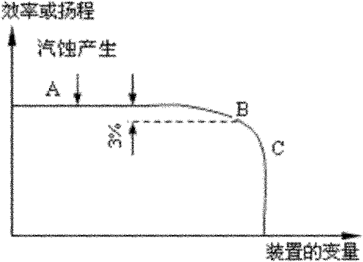
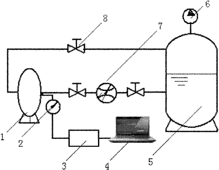
[0032] The parameters for detecting pump cavitation include noise signal of the pump, fluid pressure pulsation signal at the pump inlet, vibration signal, and pressure signal of the fluid in the pump. Among them, the fluid pressure pulsation signal at the pump inlet is an important parameter for cavitation detection. The test found that when the fluid is cavitated, the fluid pressure pulsation signal will show certain characteristics. Composite signals such as figure 2 As shown, there are many natural mode signals. The water pump cavitation measurement method of the present invention decomposes the composite signal into the sum of single-component signals with a certain intrinsic mode signal by using an Empirical Mode Decomposition (EMD) method. Since each component contains different frequency components and has different energy, a division of si...


PUM


Abstract

The invention discloses a water pump cavitation measuring method. For an eccentric water pump, a fluid pressure fluctuation signal acquired in a certain time period at the pump inlet is subject to EMD (empirical mode decomposition) so as to obtain an IMF (intrinsic mode function) component with different frequency components, thus further identifying whether cavitation occurs. The water pump cavitation measuring method comprises the following steps: assigning the fluid pressure fluctuation signal to an intermediate function; constructing an upper-lower envelope curve function by using all local maximum values and local minimum values of the intermediate function; obtaining an average envelop function and a difference function between the intermediate function and the average envelop function; judging whether the difference function meets the IMF condition of an intrinsic mode signal; if the difference function meets the IMF condition, obtaining an IMF component; otherwise, updating the intermediate function with the difference function, repeating the processes until the IMF components are obtained; and updating the intermediate function with the remaining components, and repeatingthe processes again until enough IMF components are obtained. By using the water pump cavitation measuring method, the cavitation measurement determinacy is improved, and the basis is laid for water pump re-design and prevention of further fault development.

Description

technical field [0001] The invention belongs to the field of cavitation performance measurement of water pumps, in particular to the cavitation measurement method of centrifugal water pumps. Background technique [0002] When the water pump is in operation, the local area of ​​its flow-through part is usually somewhere behind the inlet of the impeller blade. For some reason, when the absolute pressure of the pumped liquid drops to the vaporization pressure at the current temperature, the liquid starts to flow there. Vaporization produces steam and bubbles. These bubbles flow forward with the liquid, and when they reach a certain high pressure, the high-pressure liquid around the bubbles causes the bubbles to shrink sharply and even burst. When the bubbles burst, the surrounding liquid particles will fill the cavities at a high speed and collide with each other to form water hammer. This phenomenon occurs on solid walls and will cause corrosion damage to wetted parts. Ther...

Claims


Application Information

Patent Timeline
IPC IPC(8): F04D15/00
Inventor 李丽红刘艳芳徐向阳李晓利郭前进
Owner BEIHANG UNIV
Why Eureka
Try Eureka