Small dripping pipe

A dripping and pipe wall technology, applied in the direction of water shower coolers, direct contact heat exchangers, heat exchanger types, etc., can solve the problems of reduced work efficiency, uneven dripping, low efficiency of evaporators and absorbers, etc. , to achieve the effects of low equipment utilization, efficiency improvement, and efficiency reduction

Active Publication Date: 2011-04-20
CHANGSHA YUANDA BUILDING ENERGY SAVING CO LTD
View PDF1 Cites 0 Cited by
  • Summary
  • Abstract
  • Description
  • Claims
  • Application Information

AI Technical Summary

Problems solved by technology

The traditional small drip tube is an ordinary straight tube. The refrigerant water flowing out of each small hole is attached to each other due to the surface swelling force of the water, and drips from several points in a concentrated manner. The drip is uneven, and the number of drips to the point is far less Number of holes
For example: according to the length of the evaporator and absorber copper tube, the equidistant holes of the small dripping tube are designed to be 10. Due to the surface tension of the water, there are only six or seven points of dripping water, and the evaporator and absorber have 10 holes. 30% or 40% of the parts are not working due to no refrigerant dripping, that is, the above-mentioned dripping small pipes reduce the working efficiency of the evaporator and absorber by 30% or 40%
In addition, it is impossible to install the dripping tube at an absolute level in the evaporator and absorber, and there is always a deviation, which may cause the dripping liquid to flow towards the lower end, causing one end of the dripping tube to drip, and the other parts do not drip, which makes the evaporator evaporator and absorber less efficient

Method used


Image

  • Small dripping pipe
  • Small dripping pipe
  • Small dripping pipe

Examples


Embodiment Construction

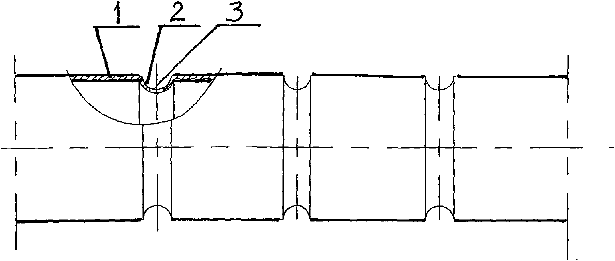
[0016] see figure 1 , the dripping small tube 1 of the present embodiment 1, its structure is: the tube wall is evenly and equidistantly processed with a plurality of annular diversion grooves 2, and the tube wall in the diversion groove 2 is drilled with small holes 3 communicating with the inside of the tube, And the aperture 3 in the diversion groove is drilled on the top of the dripping tubule.

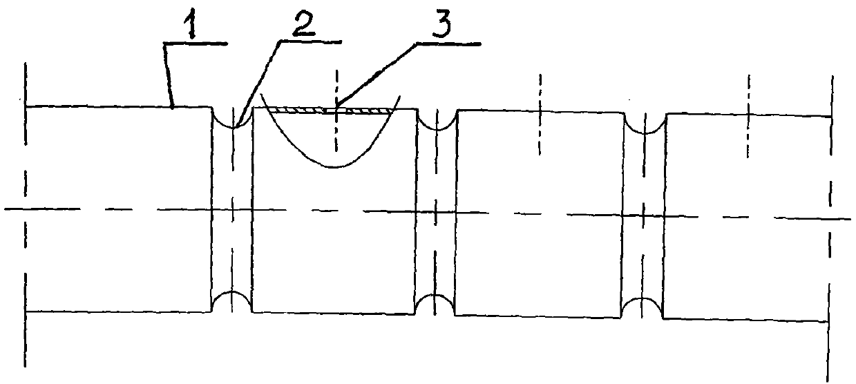
[0017] see figure 2 , the dripping small tube 1 of the present embodiment 2, its structure is: the tube wall is uniformly and equidistantly processed with a plurality of annular diversion grooves 2, and the tube wall is drilled with small holes 3 communicating with the inside of the tube, but the small holes 3 are not drilled. In the diversion tank, small holes can be drilled on the top of the drip tube or other parts.

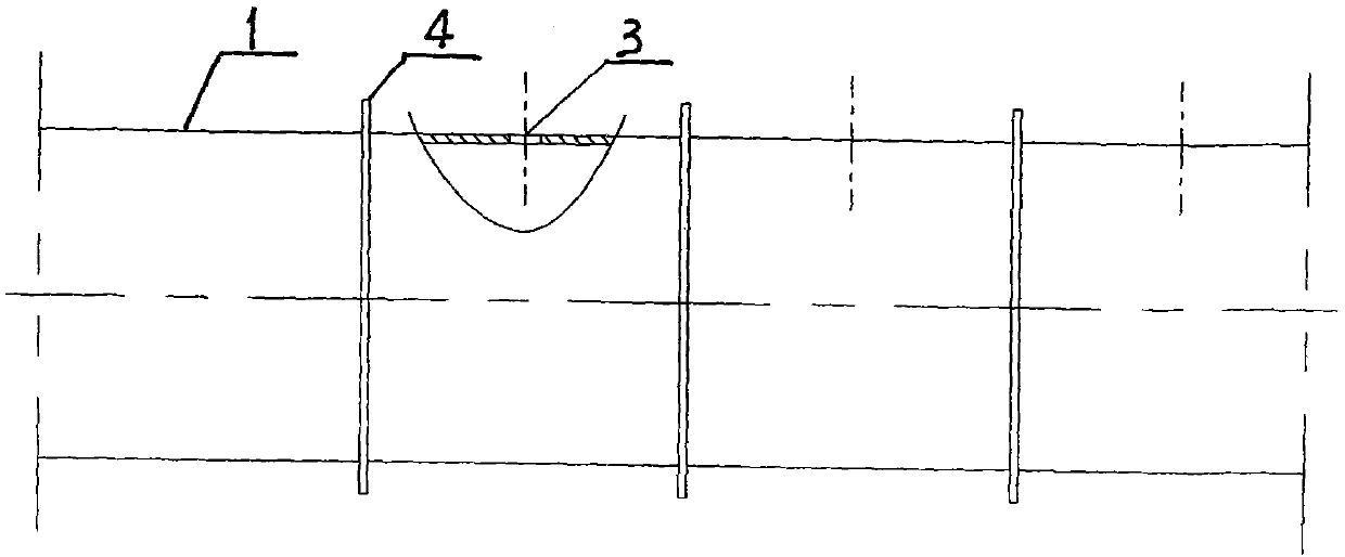
[0018] see image 3 , The dripping small tube 1 of the present embodiment 3 has a structure as follows: a plurality of annular baffles 4 are uniformly and equ...


PUM


Abstract

The invention discloses a small dripping pipe. A plurality of annular concave grooves or convex grooves or separation blades are formed on a pipe wall; small holes which are communicated with the inside of the pipe are drilled inside the concave grooves or the convex grooves or on the pipe wall outside the concave grooves or the convex grooves or the separation blades; and the concave grooves or the convex grooves or the separation blades are annularly or incompletely annularly or spirally wound on the pipe. Surface tension among liquid drops is avoided effectively, the liquid drops are prevented from being deviated and drip uniformly at equal intervals, a covering surface is large, the utilization ratios of an evaporator and an absorber are increased and the refrigerating efficiency of amain engine of an air conditioner is improved greatly.

Description

Technical field: [0001] The invention relates to a spraying device, in particular to a small dripping pipe in an evaporator and absorber system. Background technique: [0002] In the evaporator and absorber in the main system of the absorption air conditioner, there are small dripping pipes installed above the copper pipes, also known as gravity liquid distribution pipes, which are designed according to the length of the copper pipes of the evaporator and absorber below. There are one or two rows of small holes drilled in the small tube, and the refrigerant water flows out and drops onto the copper tube of the evaporator and the copper tube of the absorber. cold. The traditional small drip tube is an ordinary straight tube. The refrigerant water flowing out of each small hole is attached to each other due to the surface swelling force of the water, and drips from several points in a concentrated manner. The drips are uneven, and the number of drips to the point is far less ...

Claims


Application Information

Patent Timeline
Patent Type & Authority Applications(China)
IPC IPC(8): F28F25/06
CPCF28F25/06
Inventor 张跃
Owner CHANGSHA YUANDA BUILDING ENERGY SAVING CO LTD
Why Eureka
Try Eureka