
Non-full pipe electromagnetic flowmeter

A technology of electromagnetic flowmeter and non-full pipe, which is applied in the application of electromagnetic flowmeter to detect fluid flow, volume/mass flow generated by electromagnetic effect, etc., which can solve the problem of low precision and complexity of liquid level measurement system, increase of potential leakage points of instruments and Potential maintenance and other issues, to achieve the effect of simple and reliable mechanical structure, high precision

Inactive Publication Date: 2011-04-20
SHANGHAI HUAQIANG FULUO INSTR +1
View PDF5 Cites 6 Cited by
  • Summary
  • Abstract
  • Description
  • Claims
  • Application Information

AI Technical Summary

Problems solved by technology

This type of structure is relatively complicated in the production process, involving multiple detection and measurement components, which increases the potential leakage points and potential maintenance of the instrument itself. In addition, the accuracy of the liquid level measurement system is low, which affects the overall accuracy of the flowmeter. Generally only grade 2 accuracy

Method used


Image

  • Non-full pipe electromagnetic flowmeter
  • Non-full pipe electromagnetic flowmeter
  • Non-full pipe electromagnetic flowmeter

Examples


Embodiment Construction

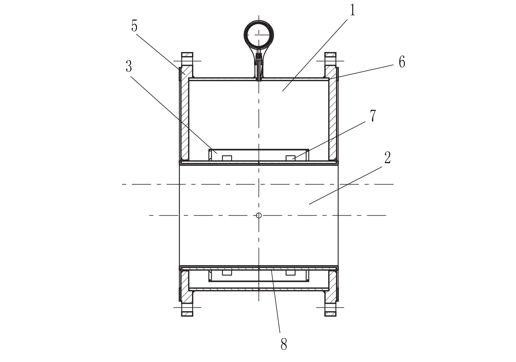
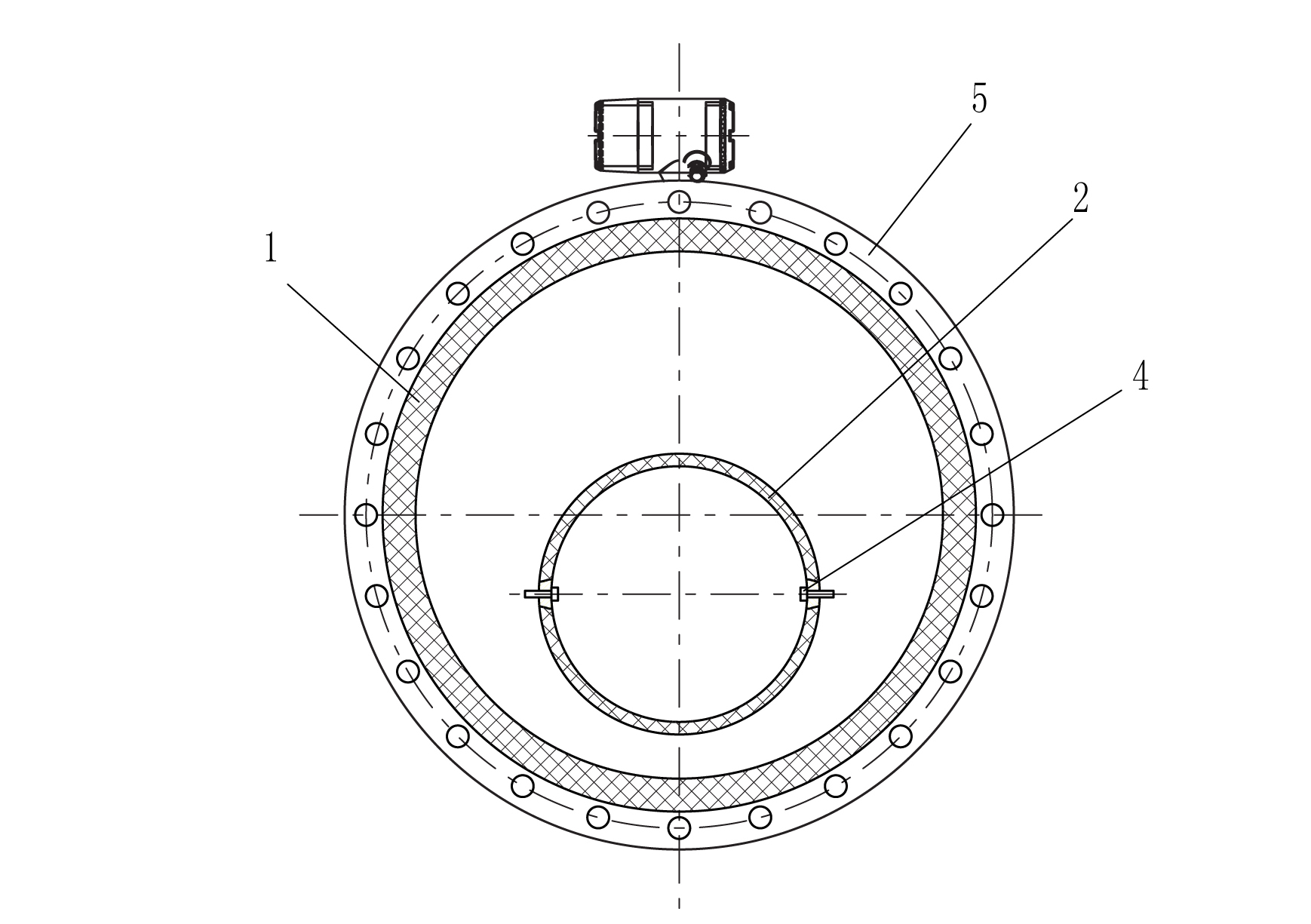
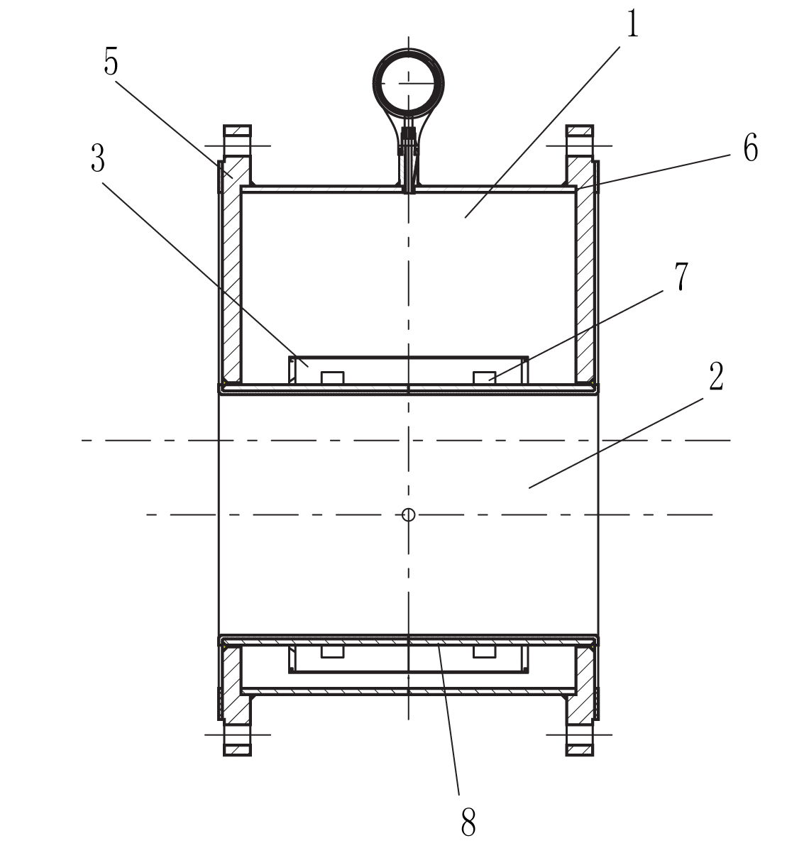
[0015] according to figure 1 , figure 2 , The present invention includes a body pipeline 1, a flow pipeline 2, an eccentric flange 5, an excitation coil 3, and an induction electrode 4 installed on the field pipeline. The outer surface of the eccentric flange 5 is provided with a groove 6 , and both ends of the body pipe 1 are embedded in the groove 6 . The body pipe 1 is provided with a flow pipe 2, and the two ends of the flow pipe 2 and the body pipe 1 are welded to the eccentric flange 5, and the center of the flow pipe 2 is located 1 / 8D below the center of the eccentric flange 5 ~1 / 6D, where D is the diameter of the body pipe. The eccentric flange 5, the body pipe 1 and the flow pipe 2 are welded externally to form a closed space. The caliber of the circulation pipe 2 is 1 / 2 of the caliber of the body pipe 1 . An excitation coil 3 is arranged between the body pipeline 1 and the circulation pipeline 2; the excitation coil 3 is divided into an upper excitation coil and...


PUM


Abstract

The invention provides a non-full pipe electromagnetic flowmeter which comprises a body pipeline arranged on an on-site pipeline, an excitation coil and eccentric flanges. The inner of the body pipeline is provided with a circulation pipeline; the circulation pipeline and the two ends of the body pipeline are welded on eccentric flanges; the center of the circulation pipeline is positioned under the center of eccentric flanges with a distance ranging from 1 / 8 D to 1 / 6 D, wherein the D is the diameter of the body pipeline. The present invention achieves the advantages of reducing fluid circulation areas in non-full pipe occasions through the structures of both eccentric flanges and the circulation pipeline, positioning at the part of the body pipeline and completely converting the non-full pipe flow measurement intoto full pipe flow measurement in application, with same use method with the traditional electromagnetic flow-meters. The invention also has a simple and reliable structure, and can guarantee a high precisionoun of 0.5 grade.

Description

technical field [0001] The invention relates to an electromagnetic flowmeter, in particular to a partially filled electromagnetic flowmeter. Background technique [0002] Traditional electromagnetic flowmeters can only measure the flow of full pipe flow, but the actual working conditions on site are more complicated, and most of them are under-full pipe conditions, especially in large-diameter pipelines such as municipal water supply and environmental protection sewage treatment. for universal. In these applications, due to the inability to accurately measure the flow rate, it has caused great economic losses to the enterprise. [0003] In order to solve the bottleneck of traditional electromagnetic flowmeters in the measurement of non-full pipes, various manufacturers have successively introduced non-full pipe electromagnetic flowmeters. The general principle is to measure the flow velocity while measuring the height of the fluid in the pipe to obtain the flow area. Multip...

Claims


Application Information

Patent Timeline
Patent Type & Authority Applications(China)
IPC IPC(8): G01F1/58
Inventor 邵思
Owner SHANGHAI HUAQIANG FULUO INSTR
Learn More