
Power supply management apparatus, electronic equipment and power supply management method

A technology for power management devices and electronic equipment, which is applied to measurement devices, data processing power supplies, and measurement flow/mass flow, etc. It can solve the problem of difficulty in judging the severity of power loads of electrical equipment, affecting the life of power modules, and large damage to power modules. problems, to achieve the effect of reducing the number of equipment, reducing system costs, and improving system performance

Inactive Publication Date: 2011-04-20
LENOVO (BEIJING) LTD
View PDF0 Cites 8 Cited by
  • Summary
  • Abstract
  • Description
  • Claims
  • Application Information

AI Technical Summary

Problems solved by technology

[0004] However, it is difficult for the user to judge the severity of the electrical load required by the electrical equipment. If the number of power modules installed in the power supply module is insufficient, the electrical load that the power supply module can currently provide is less than the electrical load required by the electrical equipment. At this time, the electrical equipment may also operate normally, but in this case, the damage to the power module is relatively large, which affects the life of the power module
In order to prevent the above situation from happening, several more power modules can be inserted in the power supply module, for example, three or four power modules, however, this approach will increase the cost of the system

Method used


Image

  • Power supply management apparatus, electronic equipment and power supply management method
  • Power supply management apparatus, electronic equipment and power supply management method
  • Power supply management apparatus, electronic equipment and power supply management method

Examples


Embodiment Construction

[0072] The specific implementation manners of the present invention will be further described in detail below in conjunction with the accompanying drawings and embodiments.

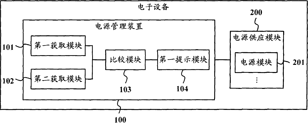
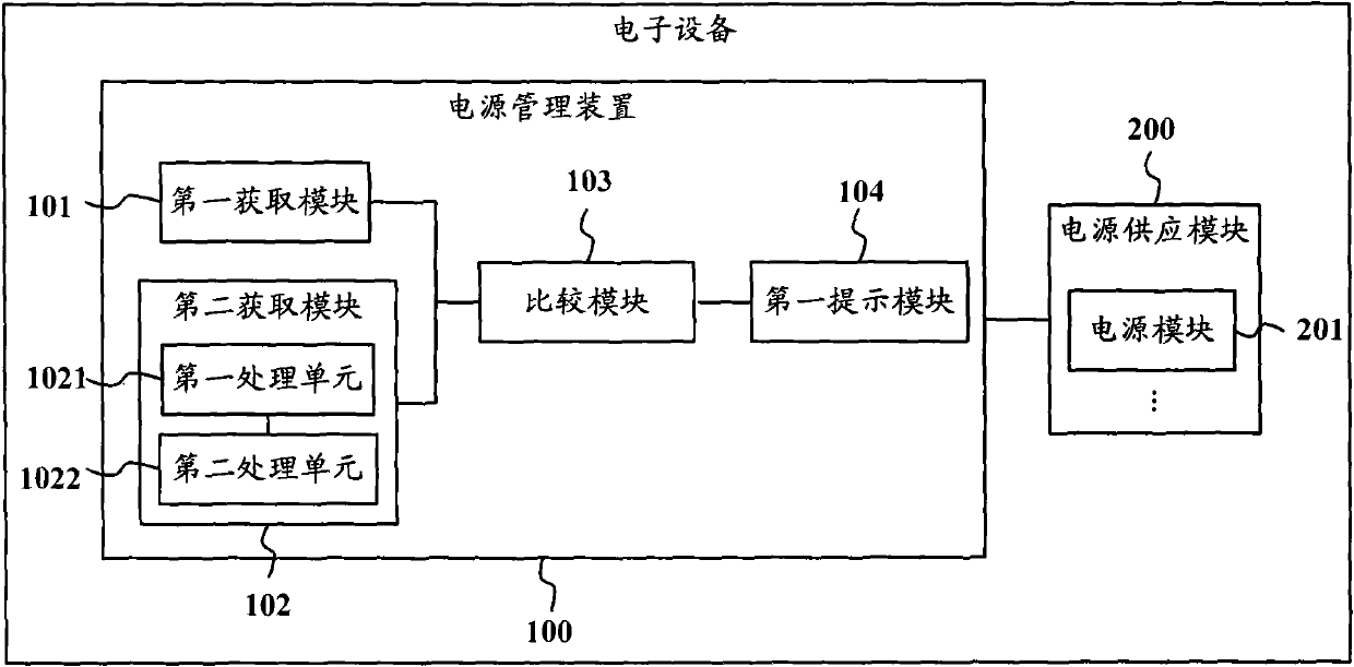
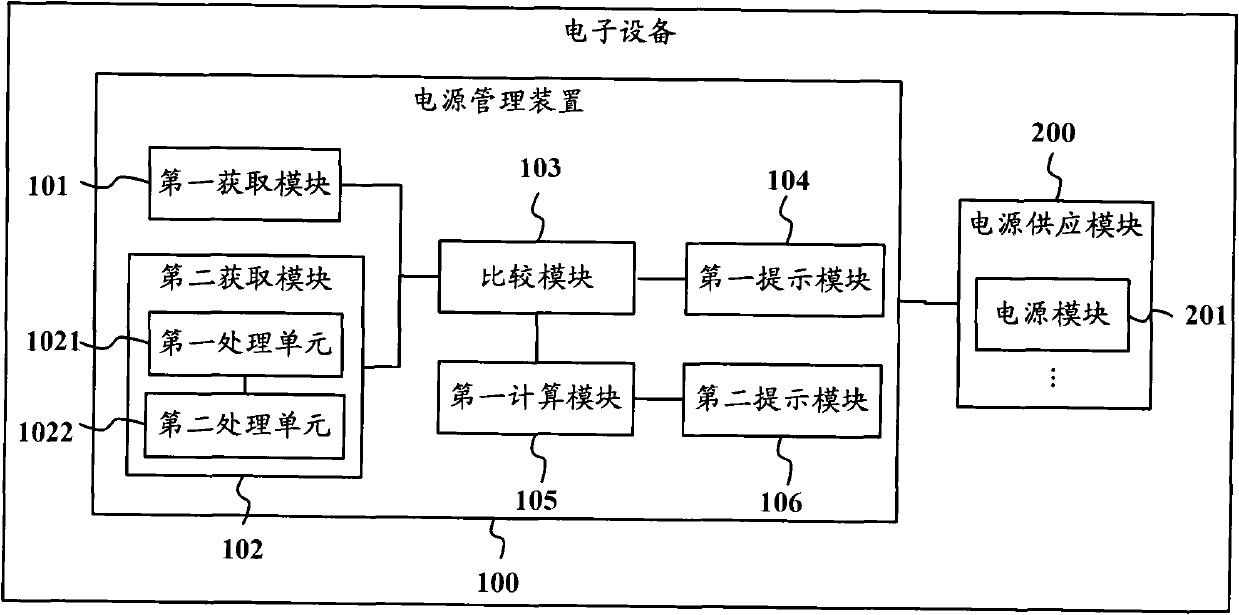
[0073] Such as figure 1 Shown is a schematic structural diagram of a power management device according to an embodiment of the present invention. The power management device 100 is applied to an electronic device, and the electronic device is an electronic device such as a communication device, a computer, or a server. The power management device 100 is connected to a power supply module 200 in the electronic device, and the power supply module 200 includes at least one power supply module 201 . When there are multiple power supply modules 201 in the power supply module 200, the multiple power supply modules 201 can provide the same electrical load (power or current). Power supply, when one of the power supply modules 201 fails to supply power, other power supply modules 201 can continue to provide power...


PUM


Abstract

The invention provides a power supply management apparatus, a piece of electronic equipment and a power supply management method. The power supply management apparatus is applied in the electronic equipment and is connected with a power supply module in the electronic equipment. The power supply module comprises at least one power module. The power supply management apparatus comprises: a first obtaining module used for obtaining electric power load needed by the electronic equipment, a second obtaining module used for obtaining electric power load provided by the power supply module at present, a comparison module used for comparing the electric power load needed by the electronic equipment with the electric power load provided by the power supply module at present so as to obtain a comparison result, and a first prompt module used for generating a prompt message in dependence on the comparison result. The prompt message is used to prompt whether the power module needs to be increased or decreased at present. The invention can determine the coupling relation between the electric power load needed by the electronic equipment and the electric power load provided by the power supply module at present so as to reduce system costs.

Description

technical field [0001] The invention relates to the technical field of power management, in particular to a power management device, electronic equipment and a power management method. Background technique [0002] A power supply module is an integral part of maintaining proper operation of various electronic devices such as communication equipment, computers or servers. In order to meet the electrical load (operating power or operating current) required by the electrical equipment, multiple power modules can be inserted into the power supply module. During normal operation, all power modules share the power supplied to the electrical equipment. When a module fails to supply power due to failure, other power modules can continue to provide power. [0003] The number of power modules inserted into the power supply module may be determined by the power load required by the power-consuming equipment. Assuming that each power module can provide a maximum power of 200W (watts),...

Claims


Application Information

Patent Timeline
Patent Type & Authority Applications(China)
IPC IPC(8): G06F1/26G06F1/28
Inventor 王军
Owner LENOVO (BEIJING) LTD
Learn More