Gain control circuit and method

A gain control circuit and gain control technology, applied in the field of control, can solve problems such as electronic gain control circuit distortion, and achieve the effect of protecting ears and preventing output signal distortion

Inactive Publication Date: 2011-04-20
TAI 1 MICROELECTRONICS CORP
View PDF4 Cites 1 Cited by
  • Summary
  • Abstract
  • Description
  • Claims
  • Application Information

AI Technical Summary

Problems solved by technology

[0005] The purpose of the present invention is to solve the technical problem that the existing electronic gain control circuit is prone to distortion

Method used


Image

  • Gain control circuit and method
  • Gain control circuit and method
  • Gain control circuit and method

Examples


Embodiment Construction

[0031] The structural features of the present invention and the achieved effects are described below with preferred embodiment drawings and detailed descriptions:

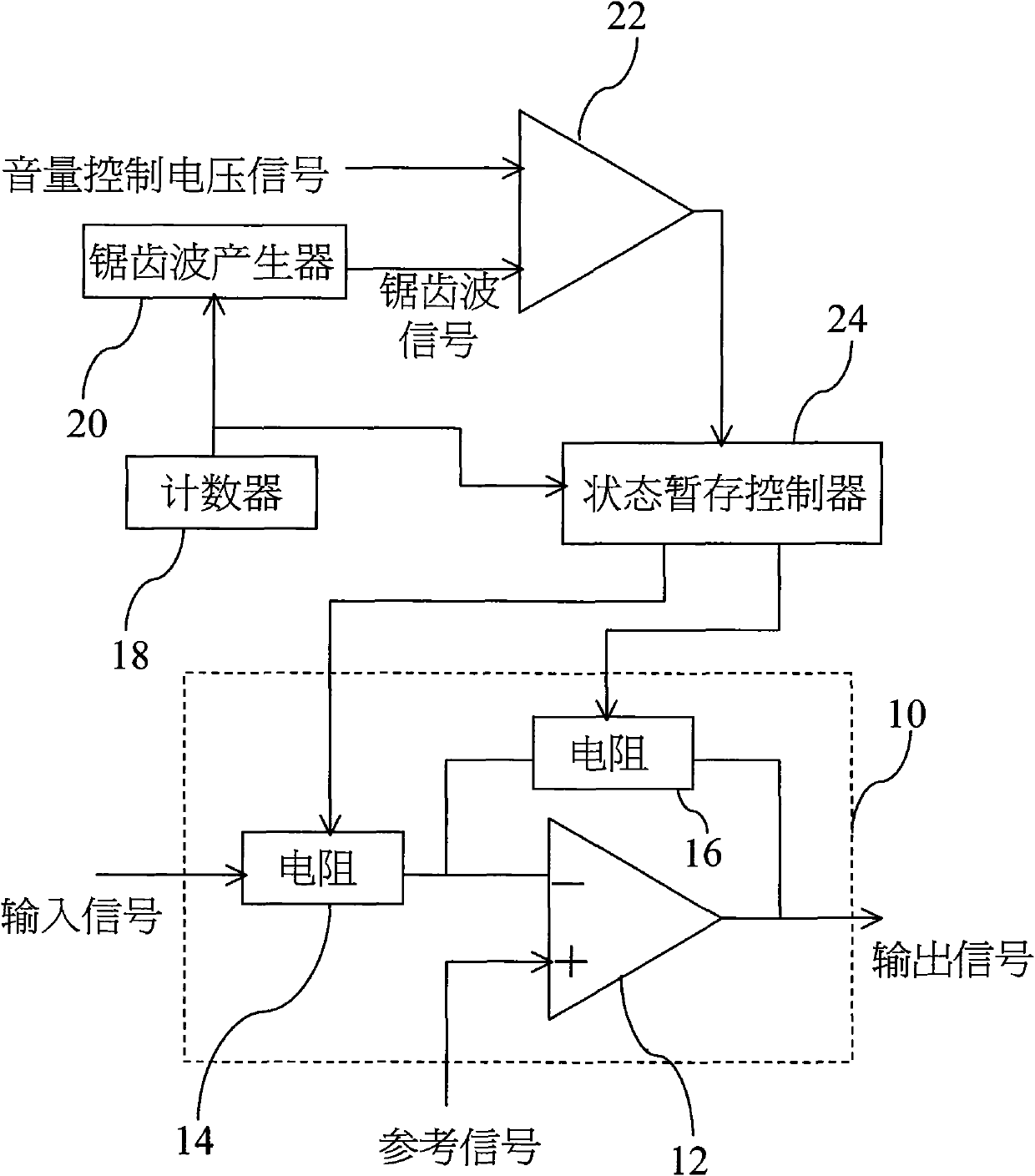
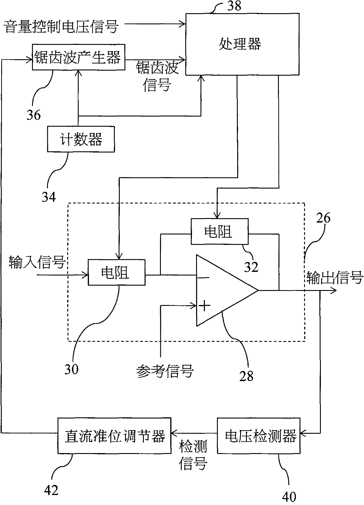
[0032]The gain control circuit of the present invention is connected with an amplifying circuit and receives a control voltage signal to determine the gain of the amplifying circuit. In the following, the control voltage signal and the amplifying circuit are respectively taken as examples of the volume control voltage signal and the audio amplifying circuit to illustrate the circuit structure and operation of the present invention.

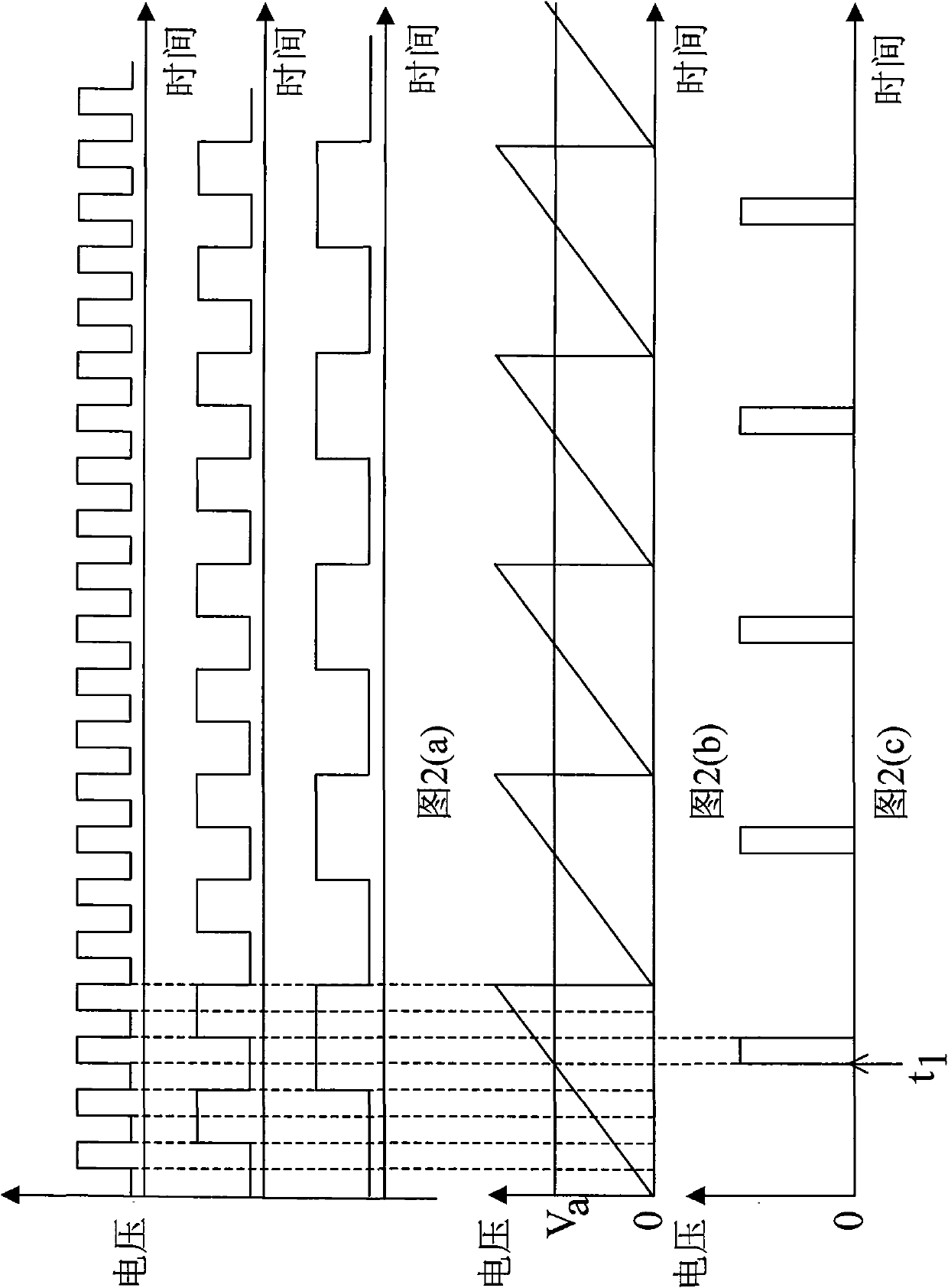
[0033] see image 3 , Figure 4(a) to Figure 4(b) ,in image 3 It is the circuit block diagram of the first embodiment; Fig. 4(a) is the signal waveform diagram output by the counter; Fig. 4(b) is the positive slope sawtooth signal and the volume control voltage signal waveform diagram. The present invention is connected to an audio amplifier circuit 26, and the amplifier circuit 26...


PUM


Abstract

The invention discloses a gain control circuit and method. The gain control method comprises the following steps of: firstly, continuously outputting a count value, generating a ramp signal accordingly, acquiring the initial count value according to the ramp signal through a voltage value generating by overlapping a control voltage signal and the ramp signal, and deciding the initial gain of an amplifying circuit accordingly; then regulating the direct-current level of the ramp signal by utilizing a detecting signal when the high voltage of the output signal of the amplifying signal is higher than a preset upper-limit detecting voltage and the low voltage of the output signal is lower than a preset lower-limit detecting voltage; and finally acquiring the count value smaller than the initial count value for the voltage value according to the ramp signal, thereby reducing the initial gain. By utilizing the mode of adjusting the direct-current level of the ramp signal, the invention not only can prevent the output signal of the audio amplifying circuit from distortion, but also can limit the magnitude of the output signal of the audio amplifying circuit, thereby protecting loudspeakers or ears.

Description

technical field [0001] The invention relates to a control technology, in particular to a gain control circuit and a gain control method thereof. Background technique [0002] Analog electronic gain control can be achieved by a Gilbert cell. The basic conversion characteristic of the Gilbert cell is Y=kX, where Y is the output signal, X is the input signal, and k is a constant. It can be seen from the above formula that the amplification factor or signal gain can be defined as Y / X, and Y / X=k, so k is the gain of the output signal Y to the input signal X. [0003] Please also refer to the following figure 1 and Figure 2(a) to Figure 2(c) , compared with the analog electronic gain control, the digital electronic gain control circuit has a larger dynamic range and more precise control on the audio amplifier circuit 10, wherein Fig. 2 (a) is an output signal waveform diagram of the counter 18; The 2nd (b) figure is a volume control voltage signal and the sawtooth wave signal ...

Claims


Application Information

Patent Timeline
Patent Type & Authority Applications(China)
IPC IPC(8): H03G3/20H03F1/32
Inventor 戴枝德
Owner TAI 1 MICROELECTRONICS CORP
Why Eureka
Try Eureka