
Link switching method and device thereof

A link switching and routing technology, applied in the communication field, which can solve the problems of unclear deployment of active and standby PWs, waste, and complex implementation.

Active Publication Date: 2011-04-20
NEW H3C TECH CO LTD
View PDF6 Cites 13 Cited by
  • Summary
  • Abstract
  • Description
  • Claims
  • Application Information

AI Technical Summary

Problems solved by technology

[0025] The disadvantage of this solution is that after receiving the MAC address revocation message, NPE2 needs to send address revocation to other LDP peers that have established LDP connections; and after receiving the MAC address revocation message, other LDP peers judge that they are at the same level Messages sent by PEs on the network (in the H-VPLS network, there are two levels) are no longer forwarded to other LDP peers, and the implementation is relatively complicated
[0027] The disadvantage of this solution is that the NPE does not know whether the active and standby PWs are deployed, and only when the active and standby PWs are deployed, the MAC address recovery message needs to be sent, otherwise it is a waste even if it is sent
[0028] It can be seen that the above two solutions, on the one hand, for U-PW switching, are implemented by relying on the LDP message of the control plane, which is realized on the control plane, and the convergence is relatively slow compared to direct processing on the data plane; Moreover, whether the protocol standard is scheme 1 or scheme 2, the processing of MAC list TLV is not very clear
On the other hand, there is no corresponding mechanism to speed up the convergence process on the UPE when the N-PW fails

Method used


Image

  • Link switching method and device thereof
  • Link switching method and device thereof
  • Link switching method and device thereof

Examples


Embodiment Construction

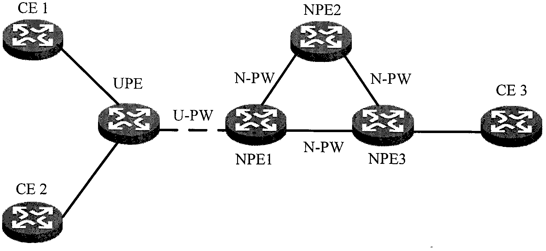
[0104] In the above prior art, when the N-PW fault occurs, such as Figure 9 As shown, the UPE must start the standby U-PW and cannot continue to use the active U-PW. Otherwise, the traffic path is as follows: Figure 10 As shown, the basic principle of split horizon is violated on NPE2. In order to comply with the basic principle of split horizon, the traffic after switching should be as follows: Figure 11 shown.

[0105] In view of the above-mentioned problems existing in the prior art, the embodiment of the present invention provides a link switching implementation scheme applied to MPLS L2VPN, which utilizes the PW Associated Channel (PW Associated Channel, PWACH) of the data plane to realize relatively complete The PW fast rerouting scheme; and the protection switching mechanism at the same level as the detection mechanism is used to avoid the participation of the control plane and improve the switching speed. In addition, the embodiment of the present invention also ...


PUM


Abstract

The invention discloses a link switching method and a device thereof, which is applied to an MPLS(Multi-Protocol Label Switching) L2VPN system including a UPE (User-facing Provider Edge) and an NPE (Network Provider Edge). The method comprises the following steps: the NPE detects the connectivity of master and slave U-PWs (Pseudo Wires) and the connectivity of an N-PW; when the NPE detects U-PW faults, an MAC (Media Access Control) address clear command is sent through the N-PW in the VSI (Visual Switch Instance) of the U-PWs, so that the NPE which receives the MAC address clear command clears the corresponding MAC address in the VSI and associated with the N-PW which transmits the MAC address clear command; when the NPE detects N-PW faults, a flow rerouting command is sent through the U-PWs in the VSI of the N-PW, so that the UPE which receives the flow rerouting command carries out U-PW switch. By using the invention, the convergence speed of the UPE of the MPLS L2VPN can be accelerated.

Description

technical field [0001] The invention relates to the communication field, in particular to a link switching method and device applied to MPLS L2VPN. Background technique [0002] MPLS (Multi-protocol Label Switching, Multi-Protocol Label Switching) is a technology that uses labels bound in IP packets to forward data packets through the network. MPLS is currently widely used in VPN (Virtual Private Network, virtual private network) aspects. The MPLS VPN network adopts label switching, and one label corresponds to one user data flow, which facilitates data isolation between users. MPLS technology can optimize the allocation of network resources to the greatest extent, automatically and quickly repair network faults, and provide high availability and reliability. [0003] MPLS-based Layer 2 VPN (ie, MPLS L2VPN) is a network for service providers to provide customers with Layer 2 services, called Multi-Protocol Label Switching Layer 2 Virtual Private Network. [0004] MPLS L2V...

Claims


Application Information

Patent Timeline
Patent Type & Authority Applications(China)
IPC IPC(8): H04L12/56H04L29/06H04L12/24H04L12/26H04L45/28
CPCH04L45/68H04L49/557H04L45/50H04L49/354H04L49/552H04L45/28
Inventor 叶金荣
Owner NEW H3C TECH CO LTD
Learn More