Moving iron type low frequency acoustic generator

A technology of moving iron and sounder, which is applied in the direction of sensors, electrical components, etc., to achieve the effect of small size and reduced volume

Inactive Publication Date: 2011-04-20
NINGBO KEPO ELECTRONICS
View PDF7 Cites 8 Cited by
  • Summary
  • Abstract
  • Description
  • Claims
  • Application Information

AI Technical Summary

Problems solved by technology

[0002] At present, the traditional electric low-frequency speaker has a fixed magnetic circuit, and the voice coil that can vibrate in the axial direction drives the diaphragm to produce sound...

Method used


Image

  • Moving iron type low frequency acoustic generator
  • Moving iron type low frequency acoustic generator

Examples


Embodiment 1

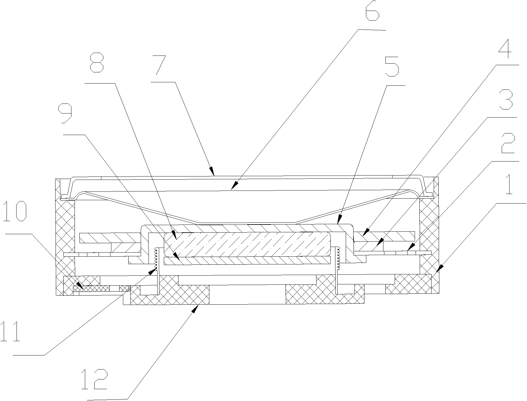
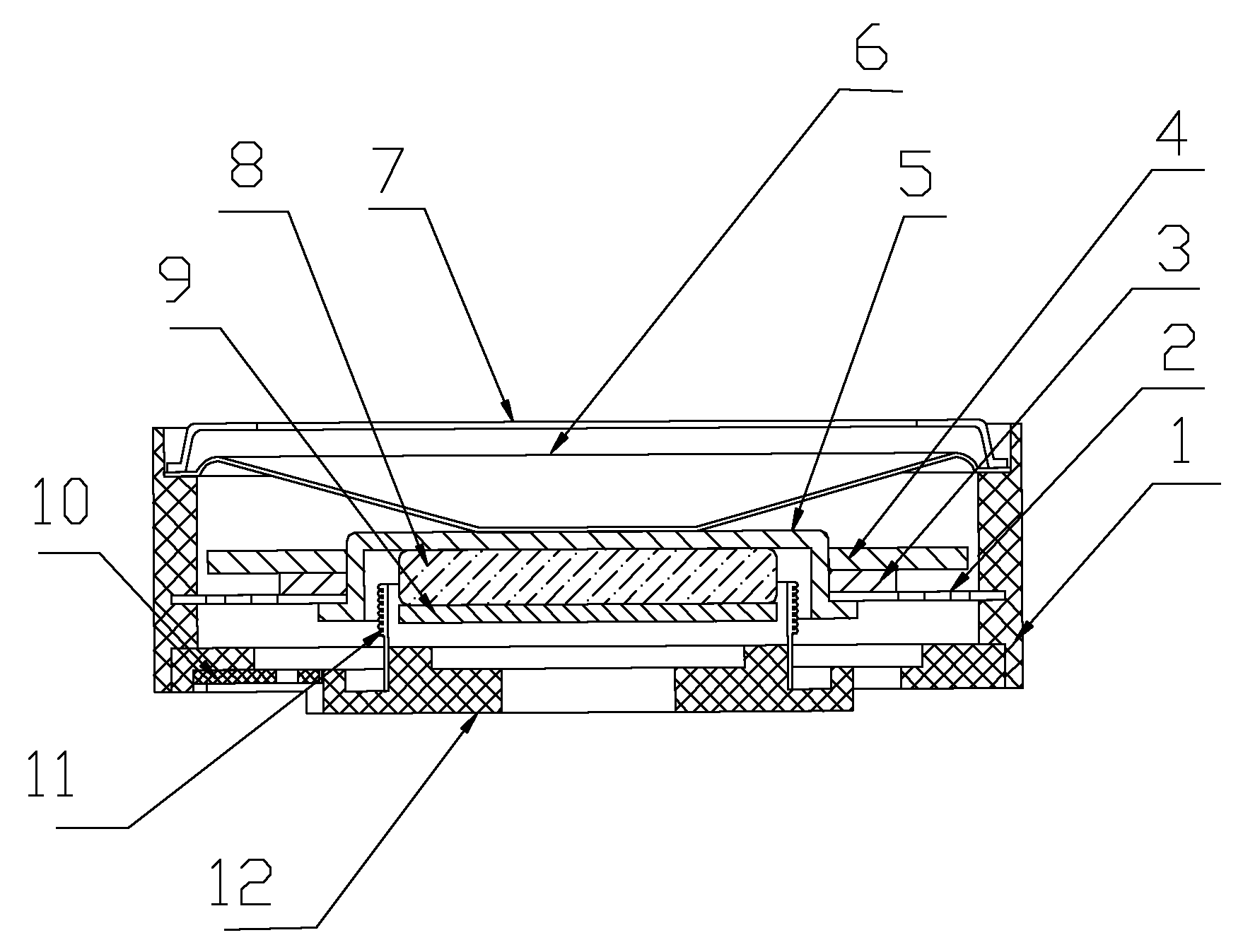
[0013] Such as figure 1 As shown, the moving iron-type low-frequency sound generator described in this embodiment includes a basin frame 1, a supporting piece 2, a spacer 3, a mass piece 4, a magnetic cup 5, a sound film 6, a front cover 7, a magnet 8, The splint 9, the printed board 10, the voice coil 11 and the back cover 12, the magnetic cup 5, the magnetic steel 8 and the splint 9 constitute a constant magnetic circuit, and the constant magnetic circuit and the supporting piece 2 constitute a vibrating magnetic circuit system. In this embodiment, the magnetic cup 5. The magnetic steel 8 and the splint 9 are glued together to form a constant magnetic circuit system; the support piece 2 adopts an insert structure and is integrally formed by injection molding with the basin frame 1. The support piece 2 is an elastic support piece, and the gasket 3 is arranged in Between the mass piece 4 and the supporting piece 2, the mass piece 4 is separated from the supporting piece 2, the ...


PUM


Abstract

The invention discloses a moving iron type low frequency acoustic generator, comprising a basin rack, a supporter, a gasket, a quality sheet, a magnetic cup, a sound film, a front cover, a magnetic steel, a plywood, a printed circuit board, a voice coil and a rear cover, wherein the magnetic cup, the magnetic steel and the plywood form a constant magnetic circuit system, the constant magnetic circuit system and the supporter forms a vibratory magnetic circuit system; the supporter and the basin rack are subjected to integrated injection moulding in a structural manner of embedded part, the gasket is arranged between the quality sheet and the supporter, the edge of the sound film is fixed on the basin rack and the center of the sound film is connected with the vibratory magnetic circuit system, the front cover is arranged outside the sound film, a magnetic gap is formed between the magnetic cup and the plywood, the printed circuit board is fixed on the basic rack, one end of the voice coil is fixed on the rear cover, and the other end of the voice coil is inserted into the magnetic gap of the constant magnetic circuit system. The moving iron type low frequency acoustic generator of the invention with small volume can mainly be applied to some products which requires relatively low frequency but not large volume, such as portable fetal sound receiver, thus the fetal sound detected by the portable fetal sound receiver can be played.

Description

Technical field [0001] The invention relates to a low-frequency sound generator with a small volume, especially a moving iron type low-frequency sound generator. Background technique [0002] At present, the traditional electric low frequency loudspeaker has a fixed magnetic circuit. The voice coil that can vibrate in the axial direction drives the diaphragm to produce sound. If a lower frequency sound is to be emitted, the diaphragm needs to be larger, usually All are above 150mm and cannot be used on products that need to be compact and easy to carry. Summary of the invention [0003] The purpose of the present invention is to provide a moving iron-type low frequency sound generator that is small in size and can emit low-frequency sounds in order to solve the above-mentioned technical deficiencies. [0004] In order to achieve the above-mentioned purpose, a moving iron type low frequency sound generator designed by the present invention includes a basin frame, a support piece, a ...

Claims


Application Information

Patent Timeline
IPC IPC(8): H04R9/06H04R9/02
Inventor 梁树棠
Owner NINGBO KEPO ELECTRONICS
Why Eureka
Try Eureka