High frequency storing case and high frequency module

A storage box, high-frequency technology, applied in waveguides, connecting devices, instruments, etc., can solve the problems of complex manufacturing process, division, and increase in quantity.

Active Publication Date: 2013-09-25
MITSUBISHI ELECTRIC CORP
View PDF1 Cites 0 Cited by
  • Summary
  • Abstract
  • Description
  • Claims
  • Application Information

AI Technical Summary

Problems solved by technology

[0005] However, this packaging structure in the prior art has many problems in terms of cost and reliability, such as increasing the number of components such as sealing rings and covers, or complicating the manufacturing processes such as soldering of the package and welding of the cover, etc.
In addition, in high-frequency bands such as the millimeter wave band, the chip size is on the order of wavelengths (about 1mm), so shielding and partitioning cannot be performed with the physical size of the cut-off cavity, and resistors / magnetic materials, etc. have to be used. expensive absorbent material

Method used


Image

  • High frequency storing case and high frequency module
  • High frequency storing case and high frequency module
  • High frequency storing case and high frequency module

Examples


Embodiment Construction

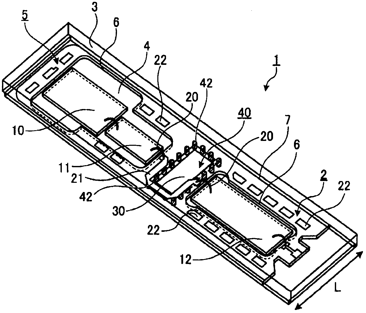
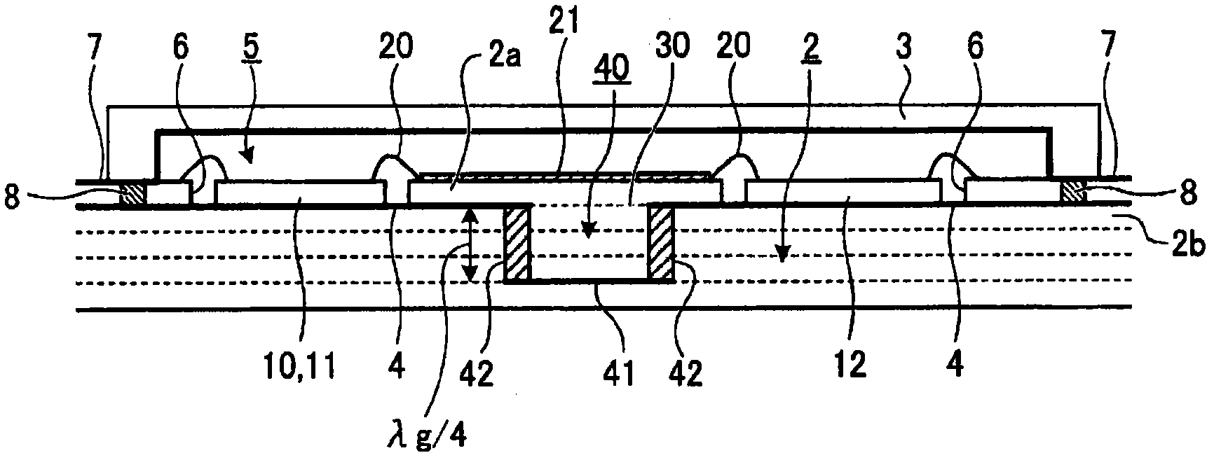
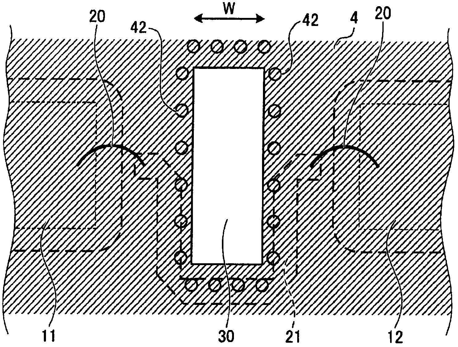
[0033] Hereinafter, referring to the accompanying drawings, the embodiments of the high-frequency storage box (or high-frequency package) and the high-frequency module according to the present invention will be described in detail. In addition, the present invention is not limited to this embodiment.

[0034] Figure 1 ~ Figure 3 It is a figure which shows the structure of embodiment of the high frequency storage case concerning this invention. In the high-frequency module 1 , a plurality of high-frequency circuits are mounted, and these high-frequency circuits operate in high-frequency bands such as a microwave band and a millimeter wave band. This high-frequency module 1 is suitable for use in FM-CW radar, for example. In addition, it can also be used by communication equipment, microwave radar, etc.

[0035] In this embodiment, as a high-frequency circuit, an oscillation circuit 10 that generates a high-frequency signal of frequency f0, an amplifier circuit 11 that ampli...


PUM


Abstract

A cavity 5 that is configured by electrically connecting an earth conductor 4 that is formed on a multilayer dielectric substrate 2 and on which a plurality of high frequency circuits 10, 11, and 12 are mounted, and a shield cover member 3; a waveguide aperture 30 that is formed on the earth conductor 4 on which the high frequency circuits 10, 11, and 12 are mounted and that is electrically coupled to the cavity 5; and an end-short-circuited dielectric waveguide 40 that is formed in a direction of layer lamination of the multilayer dielectric substrate 2, is connected to the waveguide aperture 30, and has a length approximately 1 / 4 of an effective wavelength in the substrate of a signal wave are included, and spatial isolation between the high frequency circuits is ensured by an inexpensive and simple configuration using the single cavity.

Description

technical field [0001] The present invention relates to a high-frequency storage box and a high-frequency module that constitute a cavity that is electromagnetically shielded by a multilayer dielectric substrate on which a plurality of high-frequency circuits is mounted and a shield cover covering the multilayer dielectric substrate. Background technique [0002] For high-frequency packages that carry high-frequency circuits that operate in high-frequency bands such as microwave and millimeter wave bands, they are often mounted in an inner cavity that is electrically shielded by a metal frame, etc., in consideration of operational stability and EMI (radioactive parasitic) standards. Inside. [0003] In Patent Document 1, in order to avoid spatial interference between semiconductor chips with different functions, the package assembly is divided into multiple partitions (inner cavities) by using sealing rings or individual covers. The semiconductor chips are mounted, and the ...

Claims


Application Information

Patent Timeline
Patent Type & Authority Patents(China)
IPC IPC(8): H01L23/02H01L23/12H01L25/04H01L25/18
CPCH01L2924/1423H01L2224/73265H01L2223/6627H01L23/66H01L2224/32225H01L2223/6688H01L2223/6616H01L23/043H01L23/552H01P3/16G01S7/02H01L2224/48091H01L2924/1903H01P3/121H01P5/107H01L2924/3025H01L2224/48227G01S2007/028H01L24/48H01L2924/01079H01L2224/451H01L2224/45144H01L24/45H01L24/73H01L2924/14G01S7/028H01L2924/00014H01L2924/00012H01L2924/00
Inventor 铃木拓也
Owner MITSUBISHI ELECTRIC CORP
Why Eureka
Try Eureka