Regenerative building block and diode bridge rectifier and methods

A technology of pole region and device, applied in the field of feedback automatic control structure

Active Publication Date: 2011-04-20
STMICROELECTRONICS SRL
View PDF2 Cites 3 Cited by
  • Summary
  • Abstract
  • Description
  • Claims
  • Application Information

AI Technical Summary

Problems solved by technology

Therefore, one needs a much more complica...

Method used


Image

  • Regenerative building block and diode bridge rectifier and methods
  • Regenerative building block and diode bridge rectifier and methods
  • Regenerative building block and diode bridge rectifier and methods

Examples


Embodiment Construction

[0032] The present invention includes novel devices that can be considered as regenerative building blocks (RBBs), and methods of making them. In one embodiment, the device is particularly suitable for constructing devices such as half-bridge and full-bridge rectifiers. Although those of ordinary skill in the art will immediately recognize that the present invention can be used to produce a variety of semiconductor devices, for purposes of clarity, the present invention will be described in the specification in terms of a bridge rectifier as a device and method of manufacture.

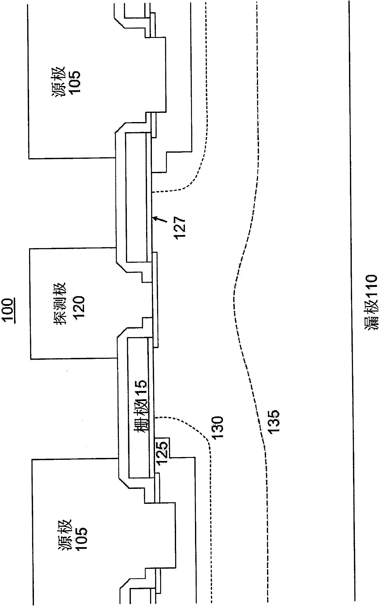
[0033] first reference figure 1 with figure 2 , showing the physical structure of the RBB structure generally indicated by 100 ( figure 1 ) and its pairs are constructed as half-bridge rectifiers ( figure 2 ) schematic diagram. Such as figure 1 As shown, RBB 100 has four electrodes: source 105 , drain 110 , gate 115 and probe 120 . The main current flows between the source and drain electrod...


PUM


Abstract

A rectifier building block has four electrodes: source, drain, gate and probe. The main current flows between the source and drain electrodes. The gate voltage controls the conductivity of a narrow channel under a MOS gate and can switch the RBB between OFF and ON states. Used in pairs, the RBB can be configured as a three terminal half-bridge rectifier which exhibits better than ideal diode performance, similar to synchronous rectifiers but without the need for control circuits. N-type and P-type pairs can be configured as a full bridge rectifier. Other combinations are possible to create a variety of devices.

Description

[0001] related application [0002] This application is linked to and claims the benefit of U.S. Provisional Application 61 / 022968, filed January 23, 2008, and U.S. Patent Application 12 / 238,308, filed September 25, 2008, and through the latter claims September 2007 US provisional application 60 / 975467 filed on the 26th entitled "Adjustable Field Effect Rectifier (Adjustable Field Effect Rectifier)" and is jointly assigned. technical field [0003] The present invention relates generally to semiconductor rectifiers, and more particularly to feedback-type automatic control structures and methods for such structures for improving the performance of diode bridges. Background technique [0004] Diode bridges, full or half bridges, are very common circuit elements to perform rectification of an oscillating output signal. A half bridge consists of two diodes and has three external electrodes. They are commonly used for output rectification in switch mode power supply circuits s...

Claims


Application Information

Patent Timeline
IPC IPC(8): H01L23/48
CPCH02M7/06H01L29/66727H01L29/7815H01L29/423H01L29/41766H01L2924/0002H01L2924/00
Inventor A·安库迪诺伍V·诺杜伍
Owner STMICROELECTRONICS SRL
Why Eureka
Try Eureka