Quick-cooling casting sand storage cabinet

A sand storage and cold mold technology, applied in the field of foundry sand treatment equipment, can solve the problems of foundry sand uniformity and water content, large equipment volume and floor area, large sand storage in the sand treatment process, etc., to improve operation Performance and service life, reduced volume and footprint, extended thermal conductivity

Inactive Publication Date: 2011-04-27
JIANGSU UNIV OF SCI & TECH
View PDF6 Cites 0 Cited by
  • Summary
  • Abstract
  • Description
  • Claims
  • Application Information

AI Technical Summary

Problems solved by technology

[0002] Casting is a common metal forming technology, and it is also an important field that reflects a country's steel processing level. In the casting production line, after the casting sand is stripped from the casting blank, it needs to be crushed and cooled and sent back to the previous forming process. The cooling rate The height of the sand treatment process and the operation level of the equipment are restricted. Most of the current processes adopt comprehensive measures such as fluidized bed, ebullated bed, water spray cooling and storage cabinet cooling. Although the fluidized bed and ebullated bed have relatively high cooling rates, they are Pneumatic energy consumption is high, and the operation noise is large; water spray cooling operation is difficult, which has a great impact on the uniformity and water content of foundry sand; although storage cabinet cooling does not have the disadvantages of the above-mentioned methods, but the cooling efficiency is low and the time is long, making The sand treatment process has a large amount of sand stored, and the equipment volume and floor space are large

Method used


Image

  • Quick-cooling casting sand storage cabinet
  • Quick-cooling casting sand storage cabinet
  • Quick-cooling casting sand storage cabinet

Examples


Embodiment Construction

[0020] A self-adaptive superheated steam saturator of the present invention will be described in further detail below in conjunction with the accompanying drawings.

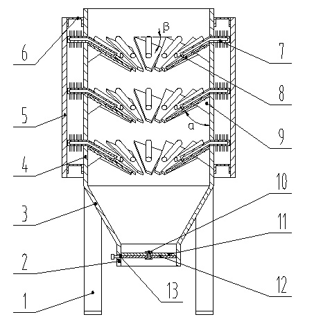
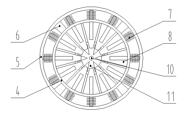
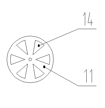
[0021] A fast-cooling casting sand storage cabinet, which consists of a support 1, a sand outlet 2, a tapered cylinder 3, an inner cylinder 4, an outer cylinder 5, an ear hook 6, a heat pipe 7, a buffer plate 8 and a rib plate 9 composition. The inner cylinder 4 is a cylinder placed vertically, the lower part of which is connected to the sand outlet 2 by a conical cylinder 3 and welded on the support 1; the sand outlet 2 is a cylindrical structure, its There is a sand-discharging mechanism inside; the sand-discharging mechanism is composed of a dynamic valve plate 12 and a static valve plate 11 with the same fan-shaped window 14. 11 is welded with the cylinder wall of the sand outlet 2, the movable valve plate 12 is located under the static valve plate 11, and the movable valve plate 12 is equipped with a handle...


PUM


Abstract

The invention discloses a quick-cooling casting sand storage cabinet which is composed of a support, a sand outlet, a conical barrel, an inner barrel, an outer barrel, an ear hook, a heat pipe, buffer plates and a reinforcing rib plate, wherein the inner barrel is a circular barrel which is vertically arranged, and the lower part of the inner barrel is connected with the sand outlet through the conical barrel and welded on the support; the inside of the sand outlet is provided with a sand outlet device; the inner wall of the inner barrel is provided with the buffer plates; the position corresponding to the place on which each buffer plate is in contact with the barrel wall is provided with a hole into which the evaporation section of the heat pipe is inserted, and the buffer plates and the barrel wall are kept in good contact; and the condensation section of the heat pipe is in a pipe finned structure and positioned in the interlayer formed by the inner barrel and the outer barrel. The invention adopts the heat pipe cooling technique, thereby reducing the volume and occupied area of the sand processor; the interlayer structure of the inner barrel and the outer barrel strengthens the function of induced draught cooling, thereby realizing cooling at zero energy consumption without destroying the structure and components of the casting sand; the fan-shaped buffer plates relieve the pressure and impact of the sand on the sand outlet valve, enhances the operating performance of the equipment and prolongs the service life of the equipment.

Description

technical field [0001] The invention relates to casting sand processing equipment, in particular to a quick-cooling casting sand storage cabinet. Background technique [0002] Casting is a common metal forming technology, and it is also an important field that reflects a country's steel processing level. In the casting production line, after the casting sand is stripped from the casting blank, it needs to be crushed and cooled and sent back to the previous forming process. The cooling rate The height of the sand treatment process and the operation level of the equipment are restricted. Most of the current processes adopt comprehensive measures such as fluidized bed, ebullated bed, water spray cooling and storage cabinet cooling. Although the fluidized bed and ebullated bed have relatively high cooling rates, they are Pneumatic energy consumption is high, and the operation noise is large; water spray cooling operation is difficult, which has a great impact on the uniformity a...

Claims


Application Information

Patent Timeline
Patent Type & Authority Applications(China)
IPC IPC(8): B22C5/08B22C5/14
Inventor 周根明周云祥陈育平孔祥雷
Owner JIANGSU UNIV OF SCI & TECH
Why Eureka
Try Eureka