Supercharge Your Innovation With Domain-Expert AI Agents!

Cutting tool and milling cutter arbor for mounting cutting tool

A technology of cutting tools and milling cutter shafts, which is applied in milling cutters, manufacturing tools, milling machine equipment, etc., can solve the problems of complex work of changing cutting edges, affecting work efficiency, and small operating space, and achieves simple structure, cost saving, and increased Effect of Coefficient of Friction

Inactive Publication Date: 2011-04-27
苏州市东南机电设备制造厂
View PDF7 Cites 1 Cited by
  • Summary
  • Abstract
  • Description
  • Claims
  • Application Information

AI Technical Summary

Problems solved by technology

In this case, when the cutting edge has been used for too long or the intensity of use is too high, and when there is a curl or a gap, the entire cutting tool can only be discarded instead of being recycled, resulting in waste of cost; second, the metal body The connection between the cutting edge and the cutting edge is screwed, which makes the work of replacing the cutting edge more complicated
[0004] On the other hand, the existing milling cutter bar or milling cutter disc for installing cutting tools usually uses screws to pass through the tool body to fix it to the milling cutter bar or milling cutter disc. When multiple cutting tools need to be installed, Using this traditional installation method requires multiple screw tightening actions, and the operation space is small, time-consuming and labor-intensive, which affects work efficiency

Method used


Image

  • Cutting tool and milling cutter arbor for mounting cutting tool
  • Cutting tool and milling cutter arbor for mounting cutting tool
  • Cutting tool and milling cutter arbor for mounting cutting tool

Examples


Embodiment Construction

[0021] The present invention will now be described in further detail in conjunction with the accompanying drawings and preferred embodiments. These drawings are all simplified schematic diagrams, which only illustrate the basic structure of the present invention in a schematic manner, so they only show the configurations related to the present invention.

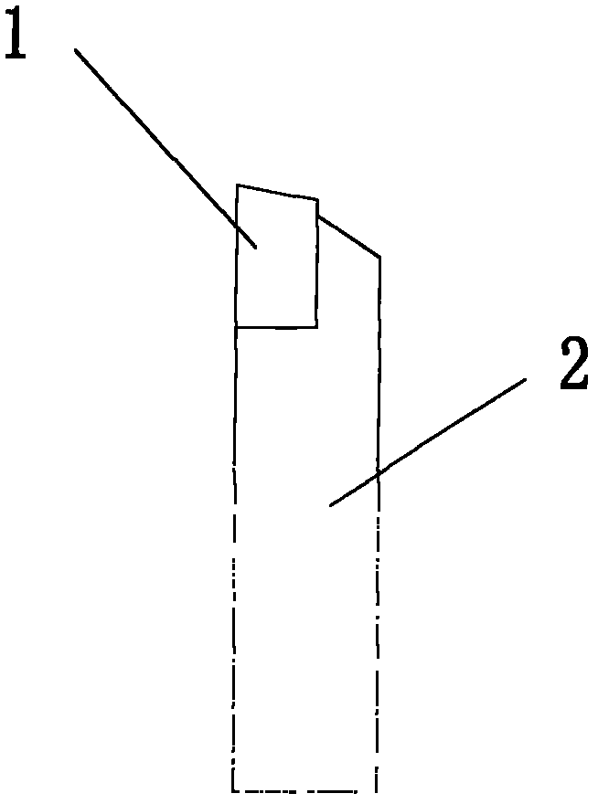
[0022] Please refer to figure 1 , the present invention discloses a cutting tool, including a tool body 2 and a cutting portion 1 . In the existing cutting tools, the tool body and the cutting part are generally integrally formed. When the cutting part has a curl or a gap, the entire cutting tool can only be discarded and cannot be reused, resulting in a waste of energy. Alternatively, the tool body 2 and the cutting part 1 are connected by screws, which makes the work of replacing the cutting edge more complicated.

[0023] In a preferred embodiment of the present invention, the tool body 2 and the cutting part 1 are conn...


PUM


Abstract

The invention relates to a cutting tool, which comprises a cutting tool body and a cutting part, wherein the cutting tool body is connected with the cutting part by welding, and the cutting part is made of an alloy material. The invention also relates to a milling cutter arbor. Milling cutter slots are uniformly arranged on the surface of the milling cutter arbor spirally; a screw hole is formed on the milling cutter arbor by clinging to the milling cutter slots; and the screw hole is formed by having an angle relative to the milling cutter slots. The cutting tool disclosed by the invention can realize cyclic utilization, save cost, and is firmer and more convenient to mount by matching with the special milling cutter arbor.

Description

technical field [0001] The invention relates to a cutting tool and a milling cutter rod used for installing the cutter, in particular to a cutting tool with high cutting strength and a milling cutter rod which is easy to install. Background technique [0002] Cutting tools are commonly used tools for cutting in mechanical manufacturing. Since the tools used in mechanical manufacturing are basically used to cut metal materials, cutting tools are required to have high strength. [0003] On the one hand, the existing cutting tools on the market are generally divided into two parts, namely the metal body and the cutting edge. The bond between the metal body and the cutting edge is generally divided into two types. First, in order to shorten the manufacturing process, the metal body and the cutting edge are generally integrally formed. In this case, when the cutting edge has been used for too long or the intensity of use is too high, and when there is a curl or a gap, the enti...

Claims


Application Information

Patent Timeline
IPC IPC(8): B23C5/20
Inventor 陈荣良
Owner 苏州市东南机电设备制造厂
Features
  • R&D
  • Intellectual Property
  • Life Sciences
  • Materials
  • Tech Scout
  • Unparalleled Data Quality
  • Higher Quality Content
  • 60% Fewer Hallucinations
Learn More