Heat exchanger

A technology of plate heat exchangers and partition plates, which is applied in the direction of heat exchanger fixation, heat exchange equipment, indirect heat exchangers, etc., can solve problems such as sealing, and achieve the effect of high sealing and mechanical stability

Inactive Publication Date: 2015-04-01
LINDE AG
View PDF6 Cites 0 Cited by
  • Summary
  • Abstract
  • Description
  • Claims
  • Application Information

AI Technical Summary

Problems solved by technology

[0010] It has been found that in such plate heat exchangers problems arise in principle when welding the headers to the transition between the side strips and the partition due to the welding material located between the side strips and the partition and In addition, sealing problems occur with increasing operating hours

Method used


Image

  • Heat exchanger
  • Heat exchanger

Examples


Embodiment Construction

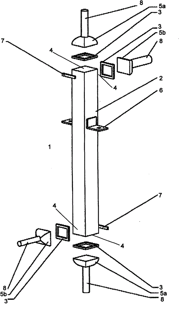
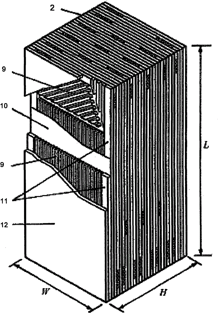
[0026] figure 1 A plate heat exchanger 1 constructed according to the method according to the invention is shown. According to this embodiment of the invention, the at least partially corrugated plates 9 and separating plates 10 with side bars 11 are stacked one above the other, provided with solder and soldered in such a way that a unit 2 is produced. The unit is closed to the outside by a cover plate 12 . On the unit 2 produced in this way, the contour of the intermediate part 3 is milled out at corresponding locations 4 . In this embodiment of the invention a frame is used as intermediate part 3 . The frame 3 is positioned in a milling out at the location 4 , provided with solder and attached by means of spot welding. The frame 3 is then soldered to the heat exchanger unit 2 in a second step. Headers 5a and 5b are welded to the frame 3, respectively. The heat exchanger 1 thus produced serves to exchange heat between two different fluids which are fed in and out via hea...


PUM


Abstract

The exchanger i.e. plate-type heat exchanger (1), has a set of rectangular separating plates arranged at a distance from each other in a stack form, so that passages are formed between the separating plates. The passages are limited at two sides by spacers e.g. side bars. Soldering agent is applied at contact points between the separating plates and the side bars. The sidebars are soldered to a block (2). Headers (5a, 5b) are welded to an intermediate piece (3) e.g. framework, which is previously soldered to the block. The block is closed with a cover plate.

Description

technical field [0001] The invention relates to a method for producing a plate heat exchanger from a plurality of rectangular partition plates arranged in a stack at a distance from one another so that channels are formed between the partition plates, wherein , the channels are limited on at least two sides by spacers (side bars), solder is applied at the contact points between the separator plates and the side bars, the stacked separator plates and side bars being welded into A unit on which there are means (manifolds) for the supply and discharge of fluid. The invention is described with reference to a plate heat exchanger made of aluminum, but can in principle be used to produce any heat exchanger having the features of the preamble of claim 1 . The invention is particularly suitable for producing plate heat exchangers based on the so-called rod-plate principle, made of stainless steel or high-temperature-resistant steel, Background technique [0002] Plate heat exchang...

Claims


Application Information

Patent Timeline
Patent Type & Authority Patents(China)
IPC IPC(8): B23P15/26B23K1/00
CPCF28F2275/06F28F21/089Y10T29/49393F28F21/083F28D9/0062F28F2275/04
Inventor R·迪茨H·艾格纳R·旺克F·温嫩
Owner LINDE AG
Why Eureka
Try Eureka