Precise positioning fixture for numerical control machining of thin-wall blade

A precise positioning and blade technology, applied in positioning devices, manufacturing tools, metal processing equipment, etc., can solve the problems of easy vibration and the inability to accurately control the blade clamping force, reduce processing deformation, improve CNC machining efficiency, The effect of improving machining accuracy and quality

Inactive Publication Date: 2011-04-27
NORTHWESTERN POLYTECHNICAL UNIV
View PDF5 Cites 15 Cited by
  • Summary
  • Abstract
  • Description
  • Claims
  • Application Information

AI Technical Summary

Problems solved by technology

[0004] In order to overcome the deficiency that the clamping force of blades in the prior art cannot be precisely controlled and vibrations are likely to occur, the present invention provides a precision positioning fixture for thin-walled blade CNC machining, which adopts a hydraulic clamping structure at the mortise root end and a blade tip workbench and positioning The fixed structure of the mandrel casting connection, thereby effectively solving the problems of the prior art

Method used


Image

  • Precise positioning fixture for numerical control machining of thin-wall blade
  • Precise positioning fixture for numerical control machining of thin-wall blade
  • Precise positioning fixture for numerical control machining of thin-wall blade

Examples


Embodiment Construction

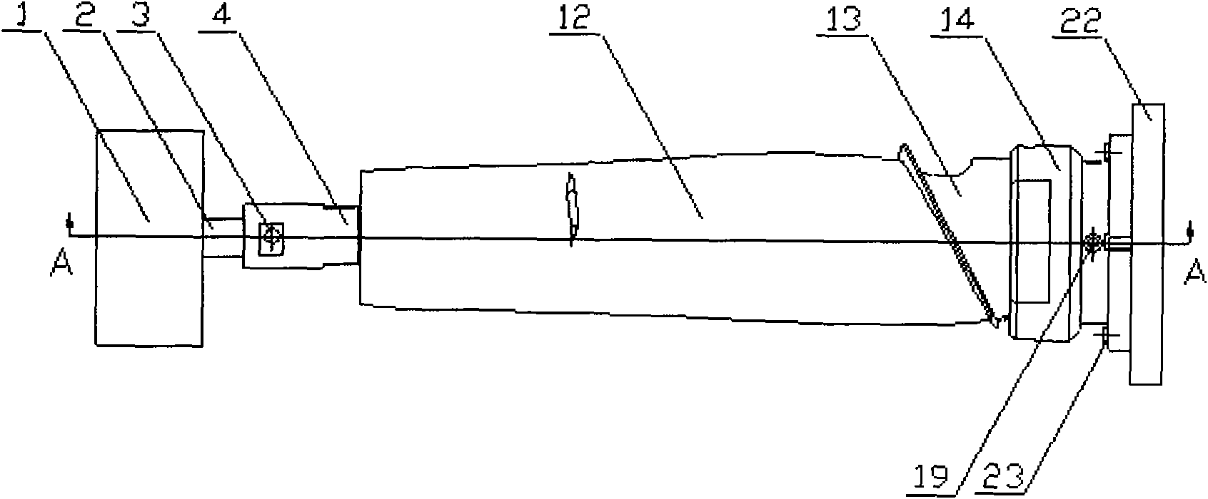
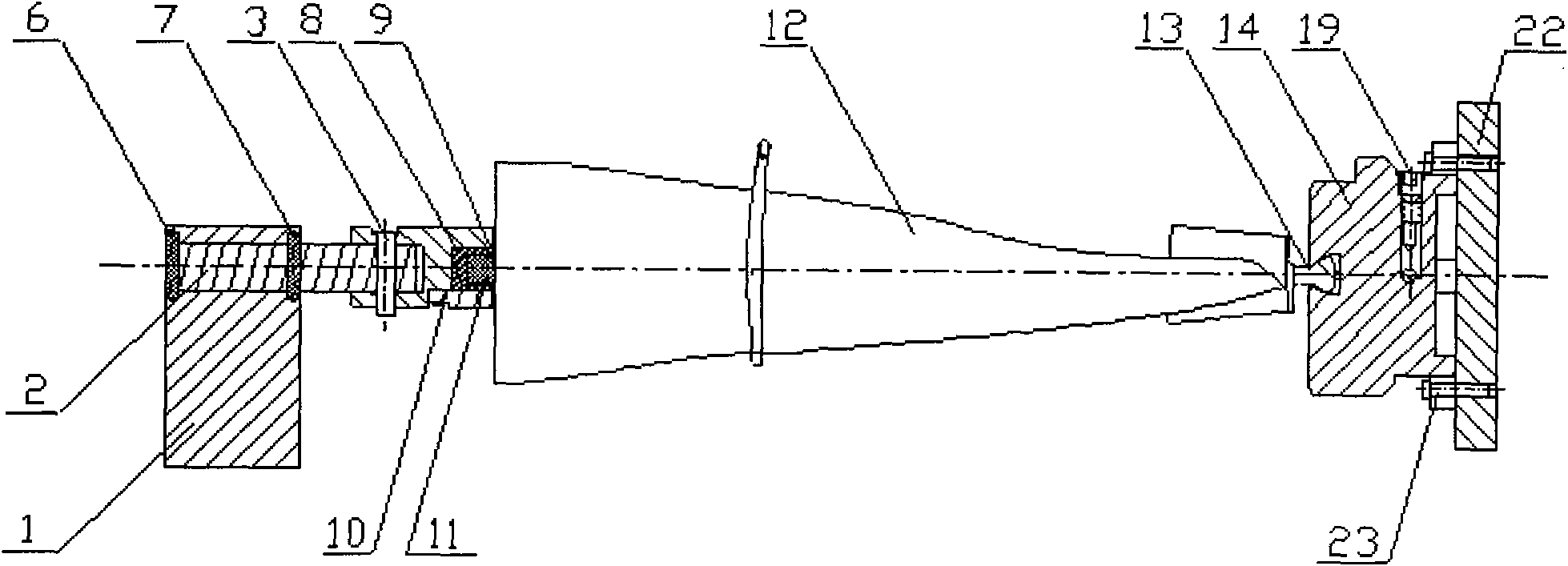
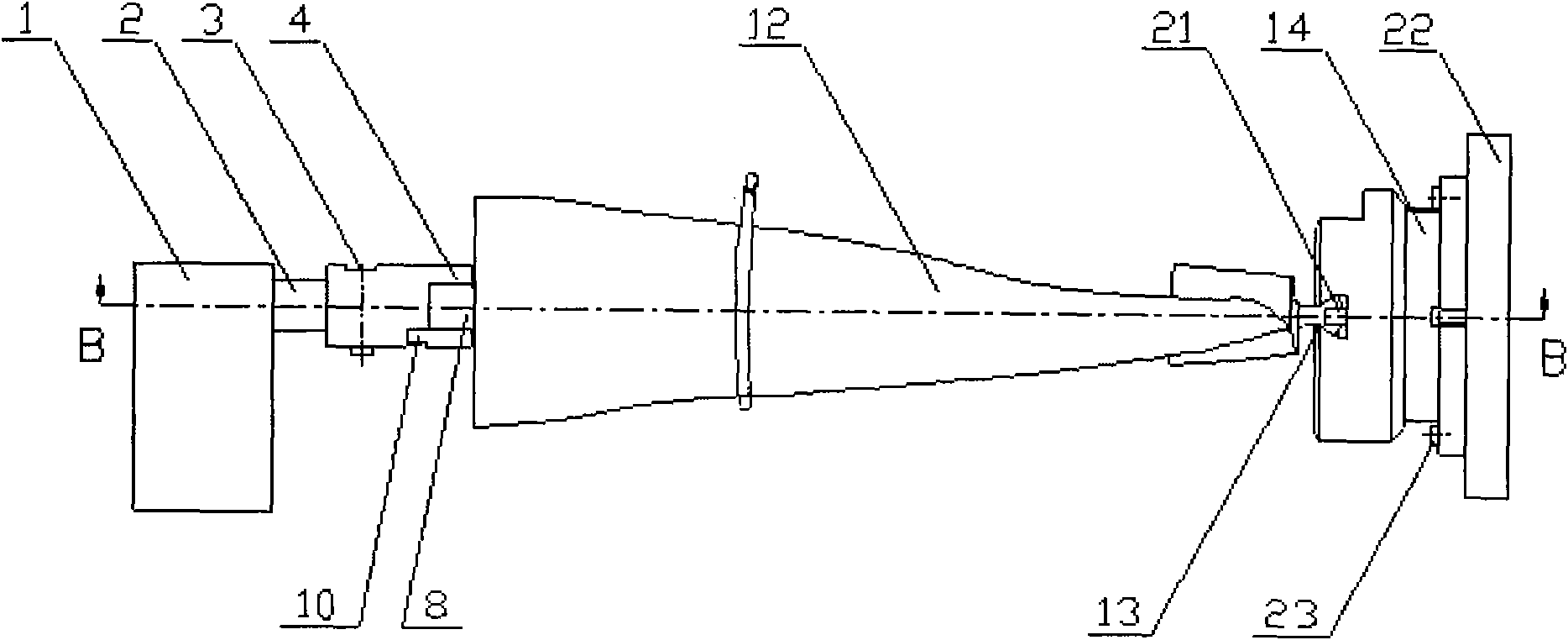
[0022] Such as Figures 1 to 5 As shown, the precision positioning fixture for CNC machining of thin-walled blades includes a clamp body, and the clamp body is composed of a tenon positioning plate 14 for clamping the tenon root 13 of the blade and a positioning mandrel 4 for clamping the tip of the blade 12 , the tenon positioning plate 14 is installed on the rotary table 22, and the tenon positioning plate 14 is provided with a blade tenon root installation groove 25, an axial oil passage 15 of the tenon positioning plate and a radial oil passage 18 of the tenon positioning plate, and the blade One end of the tenon root installation groove 25 is provided with a positioning pin 21, and the other end of the blade tenon root installation groove 25 is provided with a compression screw 24 corresponding to the blade tenon root 13, and there are two axial oil passages 15 for the tenon root positioning plate. The axial oil passages of the two mortise positioning discs are respective...


PUM


Abstract

The invention discloses a precise positioning fixture for numerical control machining of thin-wall blade. A tenon root positioning disk on a revolving workbench is provided with a blade tenon root mounting slot, an axial oil duct of the tenon root positioning disk and a radial oil duct of the tenon root positioning disk; one end of a positioning spindle is fixedly connected with a blade tip process table via a locking plate and a casting process table, the other end of the positioning disk is connected with a connecting shaft by a bolt, and the connecting shaft is installed on a tailstock by an end cap. The invention has the advantages that blades can be processed stably and have small possibility of deforming; and in addition, the precise positioning fixture provided by the invention is simple in structure, convenient for installation and high in positioning precision and can be assembled and disassembled for multiple times without affecting the positioning precision.

Description

technical field [0001] The invention relates to the technical field of aero-engine blade processing, in particular to a fixture for precision and ultra-precise numerical control cutting and processing of thin-walled blades. Background technique [0002] At present, the engines that are widely used in the aviation field are mainly turbofan engines, and the processing of the compressor and fan blades is relatively difficult. Wall structure and lightweight materials such as titanium alloy. The technological characteristics of aero-engine blades are as follows: the blade has a thin-walled structure and a complex free-form surface. In order to improve aerodynamic performance, the curved surface of the blade is severely bent and twisted. The previous setup made quite high demands. There are many types of blade processing fixtures in the prior art, usually general-purpose fixtures, adjustable fixtures, combined fixtures, etc., generally adopt a structure with one end fixed and on...

Claims


Application Information

Patent Timeline
Patent Type & Authority Applications(China)
IPC IPC(8): B23Q3/06
Inventor 刘维伟张定华任军学史耀耀汪文虎温长喜黄新春高晓娟
Owner NORTHWESTERN POLYTECHNICAL UNIV
Why Eureka
Try Eureka