
Quick measurement system for circular trace motion error based on sweep frequency laser interference

A laser interference and motion error technology, applied in the direction of measuring/indicating equipment, metal processing machinery parts, metal processing equipment, etc., can solve the problems of large interference, detection optical path cannot be blocked, and can only measure relative displacement, etc. High interference capability, no effect of guide rail measurement characteristics

Inactive Publication Date: 2011-04-27
ZHEJIANG UNIV
View PDF7 Cites 10 Cited by
  • Summary
  • Abstract
  • Description
  • Claims
  • Application Information

AI Technical Summary

Problems solved by technology

[0004] In order to overcome the shortcomings of the existing technology that the detection optical path cannot be blocked during the measurement process, the environment is greatly disturbed, only the relative displacement can be measured, and the calibration and correction of the instrument are complicated. It will not affect the measurement results even if it is broken, the absolute displacement can be measured, the calibration and correction of the instrument is simple, and the circular track motion error rapid measurement system based on frequency-sweeping laser interference

Method used


Image

  • Quick measurement system for circular trace motion error based on sweep frequency laser interference
  • Quick measurement system for circular trace motion error based on sweep frequency laser interference
  • Quick measurement system for circular trace motion error based on sweep frequency laser interference

Examples


Embodiment Construction

[0019] With reference to accompanying drawing, further illustrate the present invention:

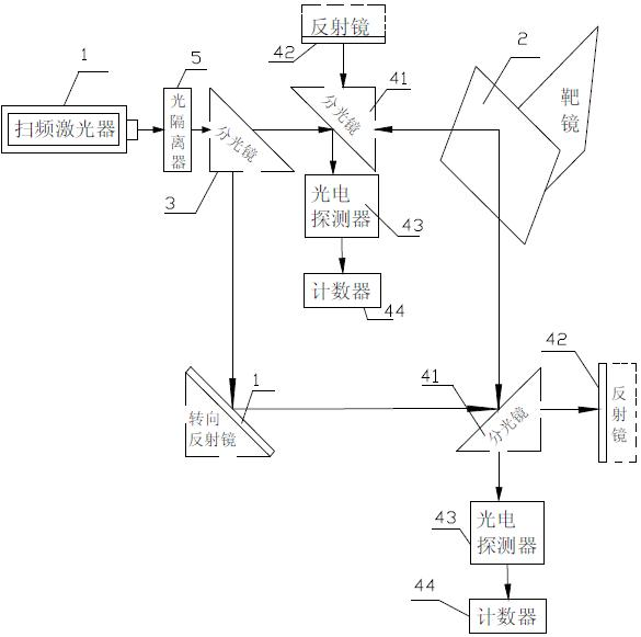
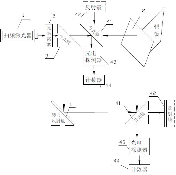
[0020] The rapid measurement system of circular trajectory motion error based on frequency-sweeping laser interference is characterized in that it includes a frequency-sweeping laser 1 that can emit light waves with continuously changing frequencies, a target mirror 2 installed on the measured guide rail of the machine tool, and a scanning between the frequency laser 1 and the target mirror 2, to obtain the detection mechanism of the error of the measured object;

[0021] Between the frequency-sweeping laser 1 and the detection mechanism, there is a total spectroscope 3 that divides the optical signal from the frequency-sweeping laser into an X-direction optical signal and a Y-direction signal; signal, an X-direction detection mechanism for detecting X-direction errors, and a Y-direction detection mechanism for obtaining Y-direction optical signals and detecting Y-direction errors;

[0...


PUM


Abstract

The invention discloses a quick measurement system for a circular trace motion error based on sweep frequency laser interference. The system comprises a sweep frequency laser, a target lens, a detection mechanism and a general spectroscope, wherein the detection mechanism comprises an X-direction detection mechanism and a Y-direction detection mechanism; each detection mechanisms comprises a sub-spectroscope, a reflector, a photoelectric detector, a counter and a processor; a first light splitting signal faces to the target lens, and a second light splitting signal faces to the reflector; thefirst light splitting signal is reflected by the target lens to form a first reflected signal; the second light splitting signal is reflected by the reflector to form a second reflected signal; and the first reflected signal and the second reflected signal are converged at the sub-spectroscope to generate an interference signal. The invention has the advantages that: the measurement result is notinfluenced even when the detection light path is blocked during the measurement, absolute displacement can be measured, and the instrument is easy to calibrate and correct.

Description

technical field [0001] The invention relates to an optical measuring instrument, in particular to a rapid detection system for circular track motion errors of machine tool guide rails. technical background [0002] One of the effective methods to evaluate the machining accuracy of machine tools is to measure the circular motion trajectory. Circular track motion is one of the common forms of motion in machining, which uses the linkage of two axes to achieve the required track. The object of the present invention is to develop a machine tool circular track motion error detection system based on frequency-sweeping laser interference. [0003] At present, there are mainly reference disc method, planar orthogonal grating method, Doppler laser measurement method, double-gauge ball bar instrument, etc. to detect the circular trajectory motion error of machine tools. The reference disc method cannot accurately calculate and distinguish the single parameter error in the circular tr...

Claims


Application Information

Patent Timeline
Patent Type & Authority Applications(China)
IPC IPC(8): B23Q17/00B23Q17/24
Inventor 曹衍龙汪琛琛汪凯巍杨将新金鹭
Owner ZHEJIANG UNIV
Learn More