
Foundation pit supporting technique for replacing temporary enclosing purlin by using plate belt of permanent structure

A technology for permanent structure and foundation pit support, which is applied in basic structure engineering, excavation, construction, etc., can solve the problem of not being able to have both the stiffness of the enclosure and the construction speed, and avoid the difficulty of construction and the rigidity of the enclosure structure. , the effect of unearthed fast

Inactive Publication Date: 2011-04-27
SHANGHAI CONSTR NO 1 GRP
View PDF6 Cites 16 Cited by
  • Summary
  • Abstract
  • Description
  • Claims
  • Application Information

AI Technical Summary

Problems solved by technology

[0006] The technical problem to be solved by the present invention is to comprehensively utilize the advantages of the forward method and the reverse method, and overcome their respective shortcomings, to provide a foundation pit support system with high rigidity, fast construction speed, and cost-saving temporary enclosure structure. It overcomes the shortcomings of the current construction of underground buildings using the forward method or the reverse method alone, and the enclosure rigidity and construction speed cannot be achieved at the same time.

Method used


Image

  • Foundation pit supporting technique for replacing temporary enclosing purlin by using plate belt of permanent structure
  • Foundation pit supporting technique for replacing temporary enclosing purlin by using plate belt of permanent structure
  • Foundation pit supporting technique for replacing temporary enclosing purlin by using plate belt of permanent structure

Examples


Embodiment Construction

[0012] The present invention will be further described below in conjunction with the accompanying drawings and embodiments.

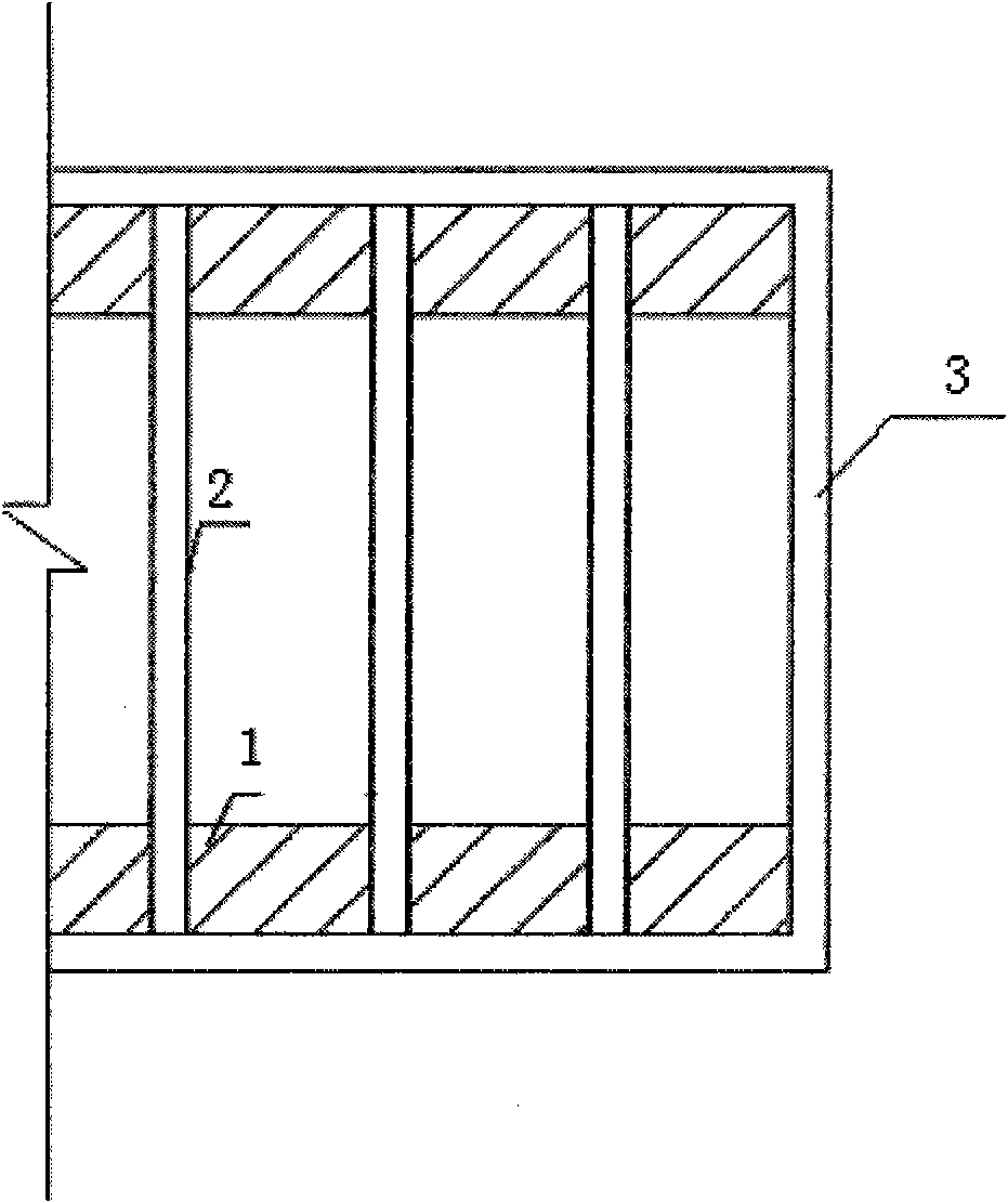
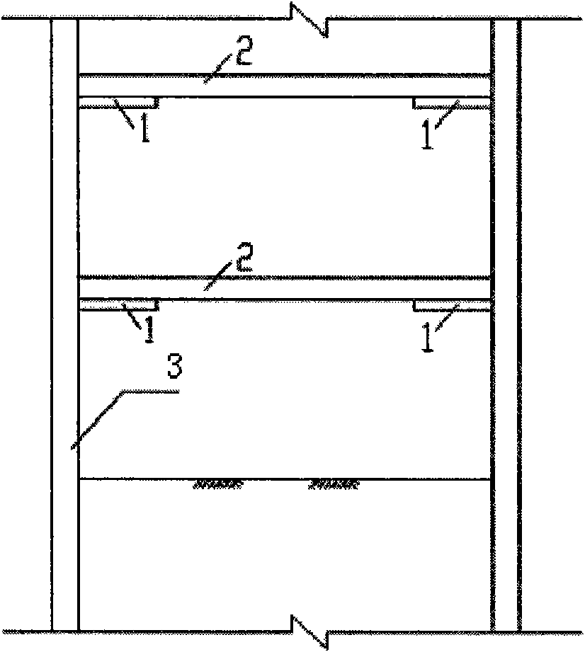
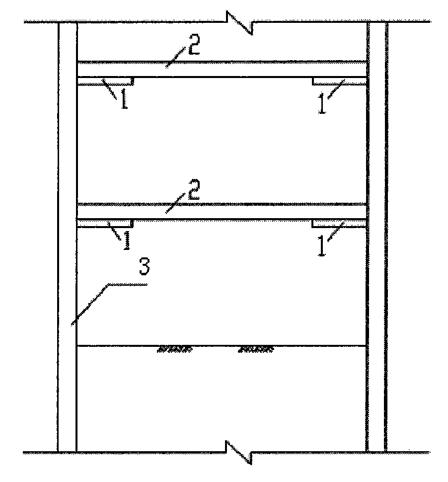
[0013] Such as figure 1 and figure 2 As shown, a foundation pit support technology in which permanent structural slabs replace temporary purlins is characterized in that: in the excavation stage of the foundation pit, the inverted slab 1 and concrete support 2 belonging to the permanent structure are used as purlins, and the foundation An enclosure structure 3 is arranged around the pit, and an upside-down slab 1 is arranged on both sides of the enclosure structure 3, and a concrete support 2 is arranged between the upside-down slabs 1 on both sides, and the two ends of the concrete support 2 are respectively connected to Envelope 3 connections. The concrete support 2 is located above the upside-down slab 1, and the bottom elevation is the same as the top elevation of the upside-down slab.

[0014] For example, a rail transit station project in Shan...


PUM


Abstract

The invention provides a foundation pit supporting technique for replacing a temporary enclosing purlin by using a plate belt of a permanent structure, which is characterized in that at the excavation stage of a foundation pit, a reverse construction plate belt belonging to a permanent structure is used as the enclosing purlin and forms a supporting system with a concrete support; an enclosing structure is arranged at the periphery of the foundation pit; the two sides of the enclosing structure are respectively provided with the reverse construction plate belt; a concrete support is arranged between the reverse construction plate belts at the two sides; and the two ends of the concrete support are also respectively connected with the enclosing structure. In the invention, the foundation pit supporting structure formed by the reverse construction plate belt used as the permanent structure and the concrete support used as a temporary structure is adopted to replace the temporary enclosing purlin adopted by the prior art, thus the techinique has the advantage of large rigidity of the enclosing structure in a reverse construction method, avoids the defects such as low rigidity of the enclosing structure of the foundation pit in a forward construction method, larger deformation of the foundation pit and large influence on the close foundation pit and the peripheral environment, but also has the advantages of fast excavation speed in the forward construction method, and avoids the defects of increased construction difficulty, slow excavation speed at the later stage and long construction period and the like in the reverse construction method due to closing of floor slabs.

Description

technical field [0001] The invention belongs to the field of underground construction engineering, and relates to a foundation pit support technology combined with a straight method and a reverse method adopted in underground engineering construction, that is, a foundation pit support technology in which permanent structural slabs replace temporary purlins. Background technique [0002] The upside-down method is a new foundation pit support technology developed in recent years. It is an effective method for constructing multi-storey basements of high-rise buildings and other multi-storey underground structures. Construction of underground diaphragm walls or other supporting structures along the axis of the basement of the building or around it, and at the same time pouring or laying down intermediate support piles and columns at relevant positions inside the building, as a support for bearing the self-weight and construction load of the upper structure before the bottom plat...

Claims


Application Information

Patent Timeline
Patent Type & Authority Applications(China)
IPC IPC(8): E02D17/20E02D17/02
Inventor 赵永光王皓周臻全李筠徐一博耿进柱
Owner SHANGHAI CONSTR NO 1 GRP
Learn More