
Foaming material filling box with reinforced layer and slurry leakage hole

A technology of foaming materials and slurry leakage holes, which is applied in the field of filling materials and foaming material inflatable boxes, and can solve problems such as unreasonable structural stress, inconvenient construction, and high cost of filling materials

Active Publication Date: 2011-04-27
徐焱
View PDF21 Cites 30 Cited by
  • Summary
  • Abstract
  • Description
  • Claims
  • Application Information

AI Technical Summary

Problems solved by technology

[0007] In the prior art, there are problems such as low hollow rate of hollow floors, unreasonable structural stress, high cost of filling materials or inconvenient construction. The purpose is to provide a foam material filling box with a reinforcement layer and a slurry leakage hole. The cross-sectional shape of the filling box is relatively perfect, which can eliminate the stress concentration around the filling material as much as possible, and can be as large as possible under the premise of ensuring the structural stress. Improve the hollow rate of the floor and ensure the quality of concrete pouring. At the same time, the product is very convenient for production, transportation and installation, and has good shock and vibration resistance.

Method used


Image

  • Foaming material filling box with reinforced layer and slurry leakage hole
  • Foaming material filling box with reinforced layer and slurry leakage hole
  • Foaming material filling box with reinforced layer and slurry leakage hole

Examples


Embodiment Construction

[0027] The present invention is realized in the following manner:

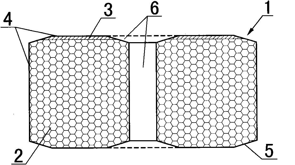
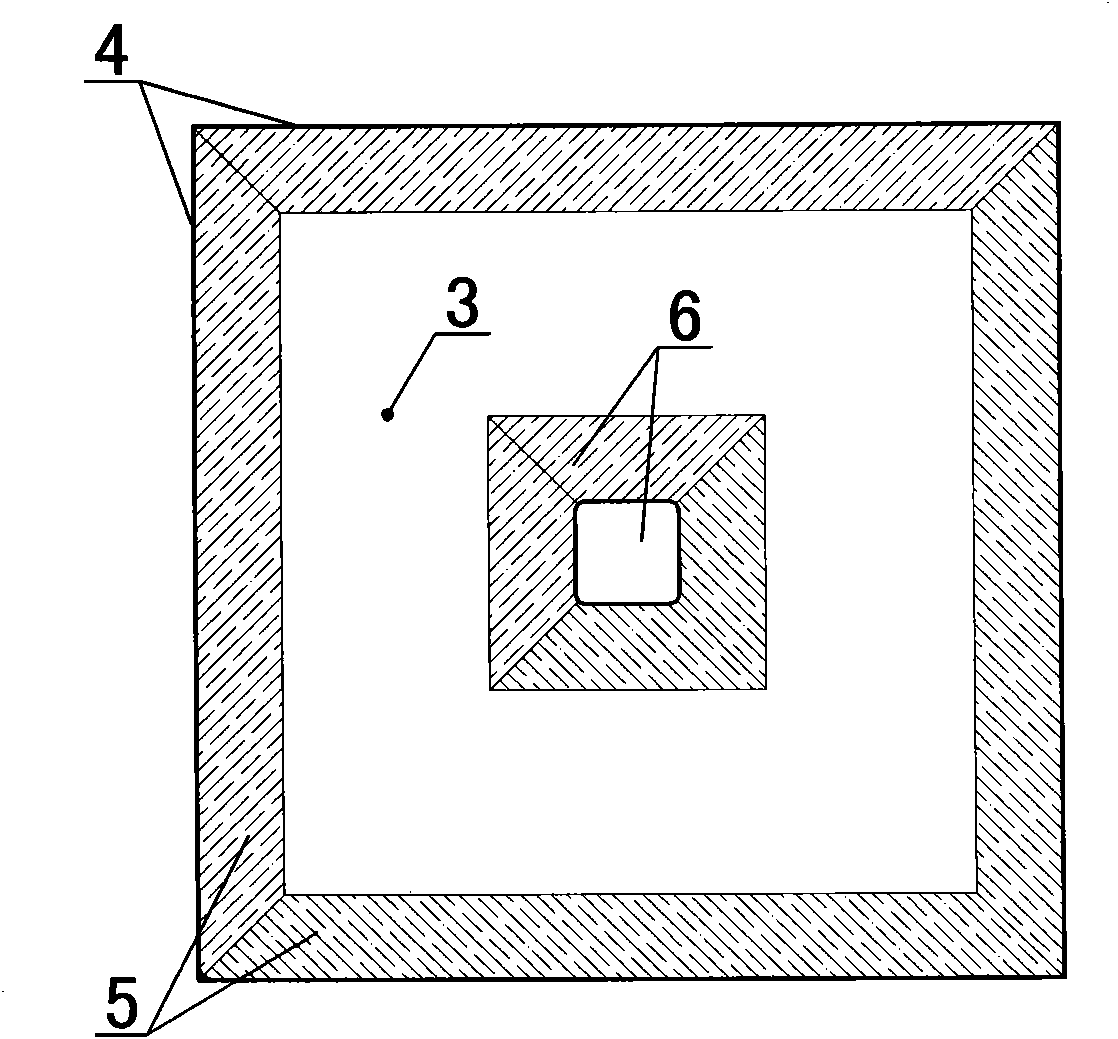
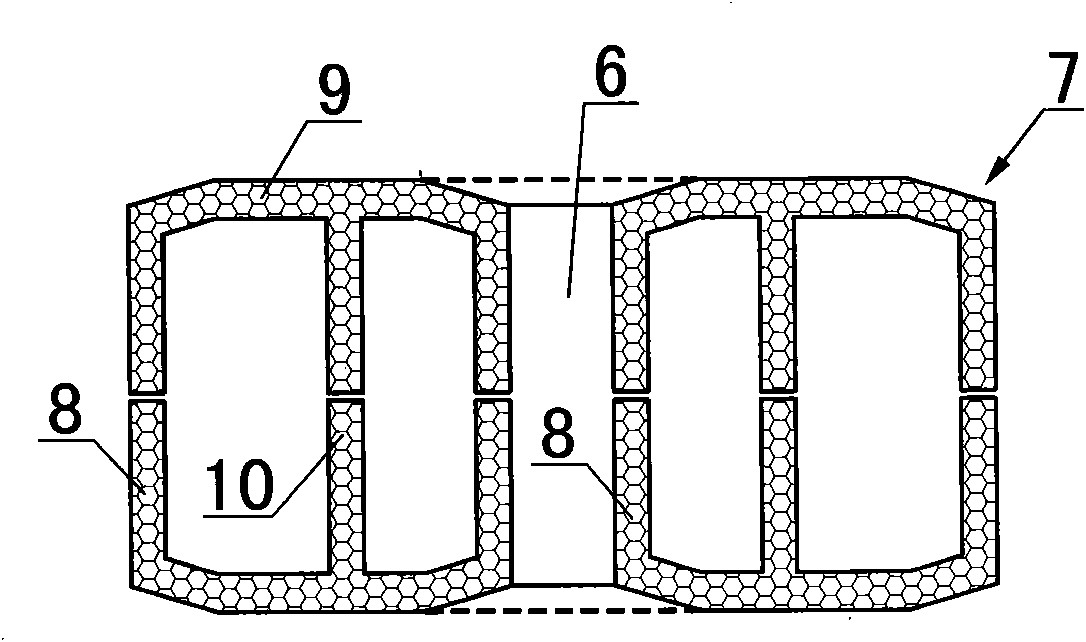
[0028] exist figure 1 , figure 2 In the shown embodiment, the main material of the body (2) of the filling box (1) is light foam material, and the planar shape of the filling box (1) is a rectangle, and the ratio of its long side to short side is less than or equal to 2, On the upper surface of the body (2), there is a hard reinforcement layer (3) with a planar shape that is annular, and an isolation layer (4) is arranged on the outer surface of the body, and the hard reinforcement layer (3) is located between the body (2) and the isolation layer (4). ), the upper and lower surfaces of the filling box (1) have cut corners or arc chamfers (5), and there is a vertical slurry leakage hole (6) in the middle of the filling box (1). The slurry leakage hole (6) The upper end of the upper end is a funnel shape with a big top and a small bottom, and the lower end of the slurry leakage hole (6) is an inverted funnel ...


PUM

PropertyMeasurementUnit
Thicknessaaaaaaaaaa

Abstract

The invention relates to a foaming material filling box with a reinforced layer and a slurry leakage hole and a manufacturing method thereof, belonging to the field of building construction. A main material of a body (2) of the filling box (1) is a light weight foaming material, the plane shape of the filling box (1) is rectangular, and the ratio of a long side to a short side is not more than 2;the upper surface of the body (2) is provided with the hard reinforced layer (3), the outer surface of the body is provided with an isolation layer (4); the hard reinforced layer (3) is located between the body (2) and the isolation layer (4); tangential angles or arc chamfers (5) are arranged at the peripheries of the upper surface and the lower surface of the filling box (1); and the middle part of the filling box (1) is provided with the vertical slurry leakage hole (6), the upper end of the slurry leakage hole (6) is in a big end up funnel shape, and the lower end of the slurry leakage hole (6) is in a big end down inverse funnel shape. In the invention, the sectional shape of the filling box meets the mechanical requirement, and the filling box is very convenient for production, transportation and installation, and has better structural reliability, shock resistance and crack resistance and favorable economical efficiency and applicability.

Description

(1) Technical field [0001] The invention relates to a filling material in a reinforced concrete hollow floor structure, in particular to a foaming material inflatable box with a reinforcing layer and a grout hole and a manufacturing method thereof, belonging to the field of general building construction. (2) Background technology [0002] In the field of construction, with the increasing number of long-span concrete structures, more and more floor slabs adopt hollow-core floor structure technology. Sometimes in order to reduce the self-weight of the structure or enhance the thermal insulation, heat insulation, sound insulation, and shock absorption effects of concrete, it is necessary to place some lightweight filler materials inside the concrete. Replacing part of the concrete with lightweight filling materials will basically not affect the mechanical performance of the structure, but it can greatly reduce the self-weight of the structure. [0003] From the construction po...

Claims


Application Information

Patent Timeline
IPC IPC(8): E04G15/06E04B5/36E04B5/17
Inventor 徐焱
Owner 徐焱
Learn More