Refrigeration cycle apparatus and hot water heater

A circulation device and refrigerant technology, applied in the direction of fluid circulation arrangements, irreversible cycle compressors, reversible cycle compressors, etc., can solve the problem of not being able to maximize the use of the performance of the supercooling heat exchanger 113 and the amount of refrigerant circulation reduction, insufficient heating capacity, etc.

Active Publication Date: 2011-04-27
PANASONIC CORP
View PDF6 Cites 11 Cited by
  • Summary
  • Abstract
  • Description
  • Claims
  • Application Information

AI Technical Summary

Problems solved by technology

[0008] However, as described in Patent Document 1, when the bypass expansion valve 121 is controlled so that the degree of superheat (Tbo-Ts) at the outlet of the subcooling heat exchanger 113 becomes the target degree of superheat, more refrigerant can be Evaporates in the subcooling heat exchanger 113, therefore, the performance of the subcooling heat exchanger 113 cannot be utilized to the fullest
That is, the effect of increasing the enthalpy in the evaporator 115 by heat exchange between the main flow refrigerant and the bypass flow refrigerant and reducing the pressure loss in the low-pressure side refrigerant flow path by bypassing the refrigerant cannot be maximized. Effect
Moreover, if the refrigerant bypassing the evaporator 115 is overheated (superheat), the volume ratio of the refrigerant sucked into the compressor 111 increases, not only the phenomenon that the circulation amount of the refrigerant decreases, but also the discharge of the compressor 111 The temperature will also increase
Therefore, when the outside air that requires a large heating capacity is low temperature, from the viewpoint of controlling the discharge temperature and ensuring reliability, the rotation speed of the compressor cannot be increased too much, and the heating capacity may be insufficient.

Method used


Image

  • Refrigeration cycle apparatus and hot water heater
  • Refrigeration cycle apparatus and hot water heater
  • Refrigeration cycle apparatus and hot water heater

Examples


no. 1 Embodiment approach

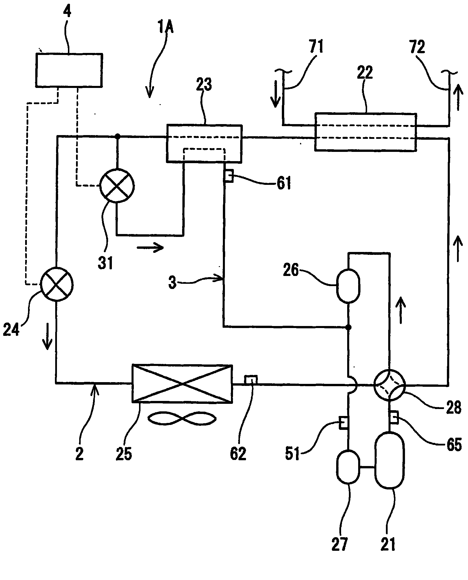
[0036] figure 1 A refrigeration cycle apparatus 1A according to the first embodiment of the present invention is shown. This refrigeration cycle apparatus 1A includes: a refrigerant line 2 for circulating a refrigerant; a bypass 3 ; and a control device 4 . As the refrigerant, for example, a non-azeotropic mixed refrigerant such as R407C, a near-azeotropic mixed refrigerant such as R410A, or a single refrigerant can be used.

[0037] The refrigerant line 2 is formed by connecting a compressor 21 , a condenser 22 , a subcooling heat exchanger 23 , a main expansion valve (main expansion mechanism) 24 , and an evaporator 25 in a tubular shape with piping. In the present embodiment, a sub-accumulator 26 and a main accumulator 27 for separating gas and liquid are provided between the evaporator 25 and the compressor 21 . A four-way valve 28 for switching between a normal operation and a defrosting operation is provided in the refrigerant line 2 .

[0038] In this embodiment, th...

no. 2 Embodiment approach

[0068] Figure 4 A refrigeration cycle apparatus 1B according to a second embodiment of the present invention is shown. In this embodiment, the same members as those in the first embodiment are given the same reference numerals, and description thereof will be omitted.

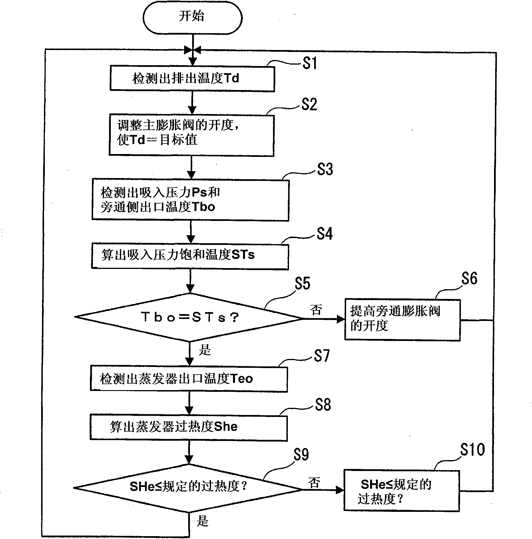
[0069] Also in this embodiment, as in the first embodiment, the control device 4 controls the bypass expansion mechanism 31 during normal operation so that the bypass pipe side outlet temperature Tbo detected by the first temperature sensor 61 becomes The saturated temperature STs under the pressure of the refrigerant sucked into the compressor 21, and the degree of superheat SHe at the outlet of the evaporator 25 calculated from the outlet temperature Teo of the evaporator detected by the second temperature sensor 62 is set in advance. below the specified superheat. However, in the present embodiment, the control device 4 detects that the bypass pipe side outlet temperature Tbo detected by the first tempera...

other Embodiment approach

[0084] In the above-mentioned first and second embodiments, the main expansion valve 24 is controlled so that the discharge temperature Td becomes the target value, however, the method of controlling the main expansion valve 24 is not limited to this. For example, the main expansion valve 24 may be controlled so that the pressure of the refrigerant discharged from the compressor 21 becomes a target value. Alternatively, the main expansion valve 24 may also be controlled according to the degree of superheat at the outlet of the compressor 21 or the degree of subcooling at the outlet of the condenser 22 .

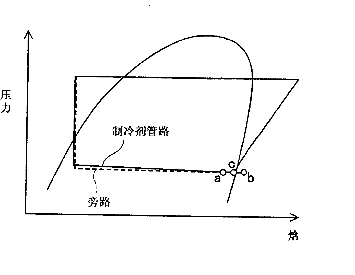
[0085] The bypass 3 does not need to branch from the refrigerant line 2 between the subcooling heat exchanger 23 and the main expansion valve 24 , and may branch from the refrigerant line 2 between the condenser 22 and the subcooling heat exchanger 23 .

[0086] Furthermore, the main expansion mechanism and the bypass expansion mechanism of the present invention do not have t...


PUM


Abstract

A refrigeration cycle apparatus 1A includes: a refrigerant circuit 2 provided with a subcooling heat exchanger 23; a bypass passage 3 extending through the subcooling heat exchanger 23; and a controller 4 for controlling a main expansion means 24 in the refrigerant circuit 2 and a bypass expansion means 31 in the bypass passage 3. The bypass expansion means 31 is controlled so that a bypass side outlet temperature conforms to a saturation temperature at a pressure of a refrigerant to be drawn into a compressor 21, and a degree of superheat at an outlet of an evaporator 25 calculated based on an evaporator outlet temperature is equal to or lower than a predetermined degree of superheat.

Description

technical field [0001] The present invention relates to a refrigerating cycle device for subcooling refrigerant flowing out of a condenser and a warm water heating device using the refrigerating cycle device. Background technique [0002] In the past, there was a refrigeration cycle device, which installed a subcooling heat exchanger on the downstream side of the condenser of the refrigerant pipeline, and made the expanded refrigerant flow into the subcooling heat exchanger to supercool the refrigerant flowing out of the condenser. of refrigerant. For example, disclosed in Patent Document 1 Image 6 A refrigeration cycle apparatus 100 is shown. [0003] This refrigeration cycle apparatus 100 includes a refrigerant line 110 and a bypass 120 for circulating a refrigerant. The refrigerant line 110 is configured by connecting the compressor 111 , the condenser 112 , the subcooling heat exchanger 113 , the main expansion valve 114 , and the evaporator 115 in a ring shape using ...

Claims


Application Information

Patent Timeline
Patent Type & Authority Applications(China)
IPC IPC(8): F25B1/00F25B41/06F25B49/02
CPCF25B2339/047F25B2700/2101F25B2400/13F25B40/02F25B2600/2509F25B2700/2103F25B13/00F25B2500/08F25B2500/31
Inventor 森胁俊二青山繁男冈座典穗谏山安彦
Owner PANASONIC CORP
Why Eureka
Try Eureka